
Large 1/12 Scale Kit
This is the fifth part of the Revell 1969 Camaro Z/28 3in1 1/12 Scale 85-2812.
You might recall from the previous post, I ran into an issue with the exhaust manifolds aligning properly with the engine once it was installed. My solution to this issue was to build the rest of the exhaust and muffler parts to help keep everything in place and straightened out.
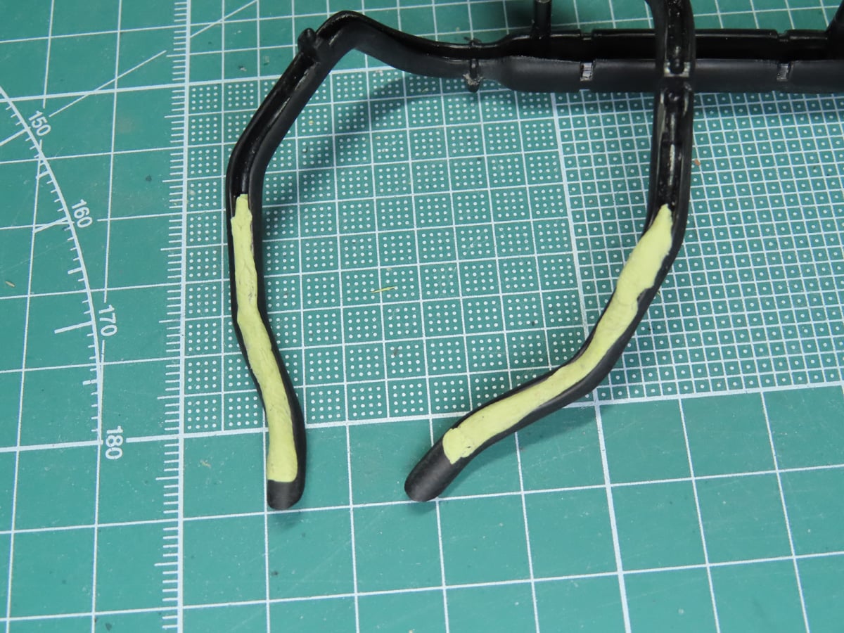
The exhaust parts are U-shaped with the backing hollowed out to save on plastic. And this isn’t a bad thing since you won’t see most of this once the parts are installed onto the chassis. However, I think you might see part of the opened exhaust near the rear of the car.
So I filled in a small section with Milliput 2-part sculpting clay. You simply knead the yellow and grey clay together, and once they are properly mixed together, the Milliput is placed into the opening of the exhaust.

To help smooth out the Milliput, I used the AK Interactive Silicone Brushes AKI 9088, which worked really well to level and manipulate the Milliput.
Once the Milliput had hardened completely, I sanded it smooth using various grits of Tamiya Sanding Sponges. And once I was satisfied with the sanding, the parts were finally primed with Tamiya Liquid Surface Primer Gray 87075.
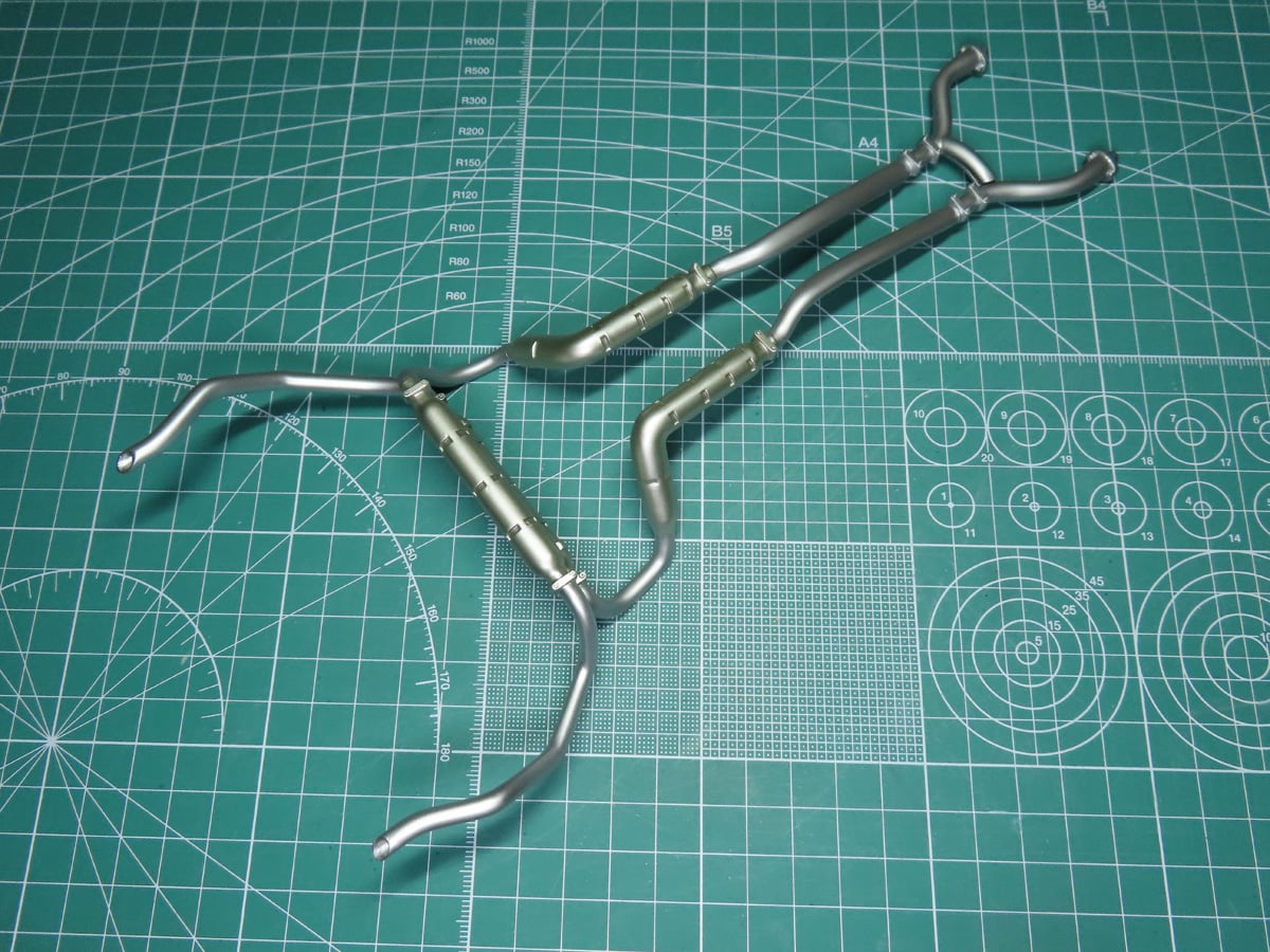
Most of the exhaust was painted with Tamiya LP-11 Silver, and the back section was painted with Tamiya LP-72 Mica Silver. The small muffler sections were painted with Tamiya LP-63 Titanium Silver.
With the exhaust sections glued together, I was ready to add this section to the model.
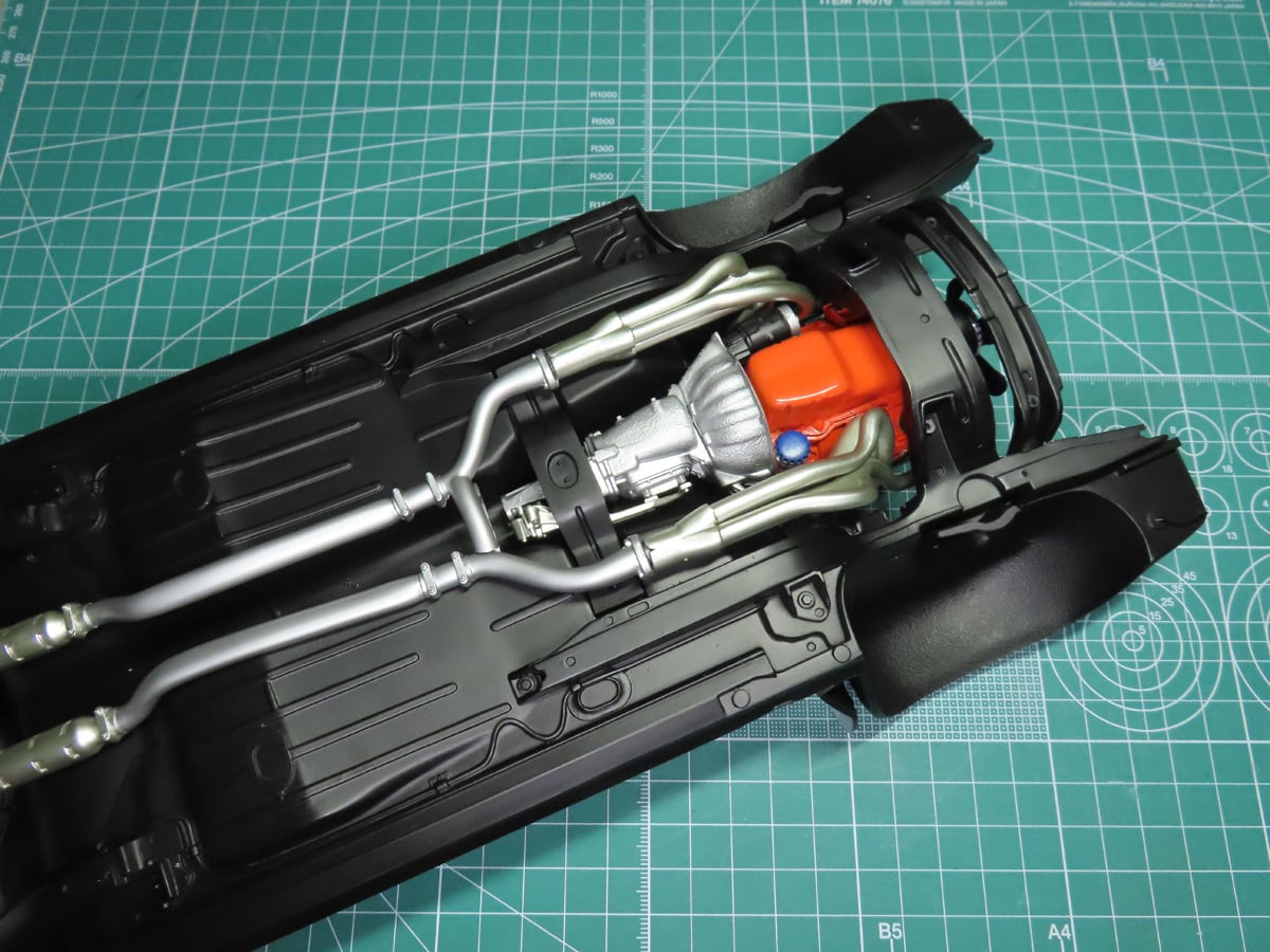
The exhausts were glued in place near the back of the chassis. Once that had dried properly, I was ready to connect the exhaust manifolds. This helped greatly to align the parts, and it made it easier for me to glue the manifolds back onto the engine.
I used a bit of BSI CA glue to connect the parts together and ensure a very strong bond.
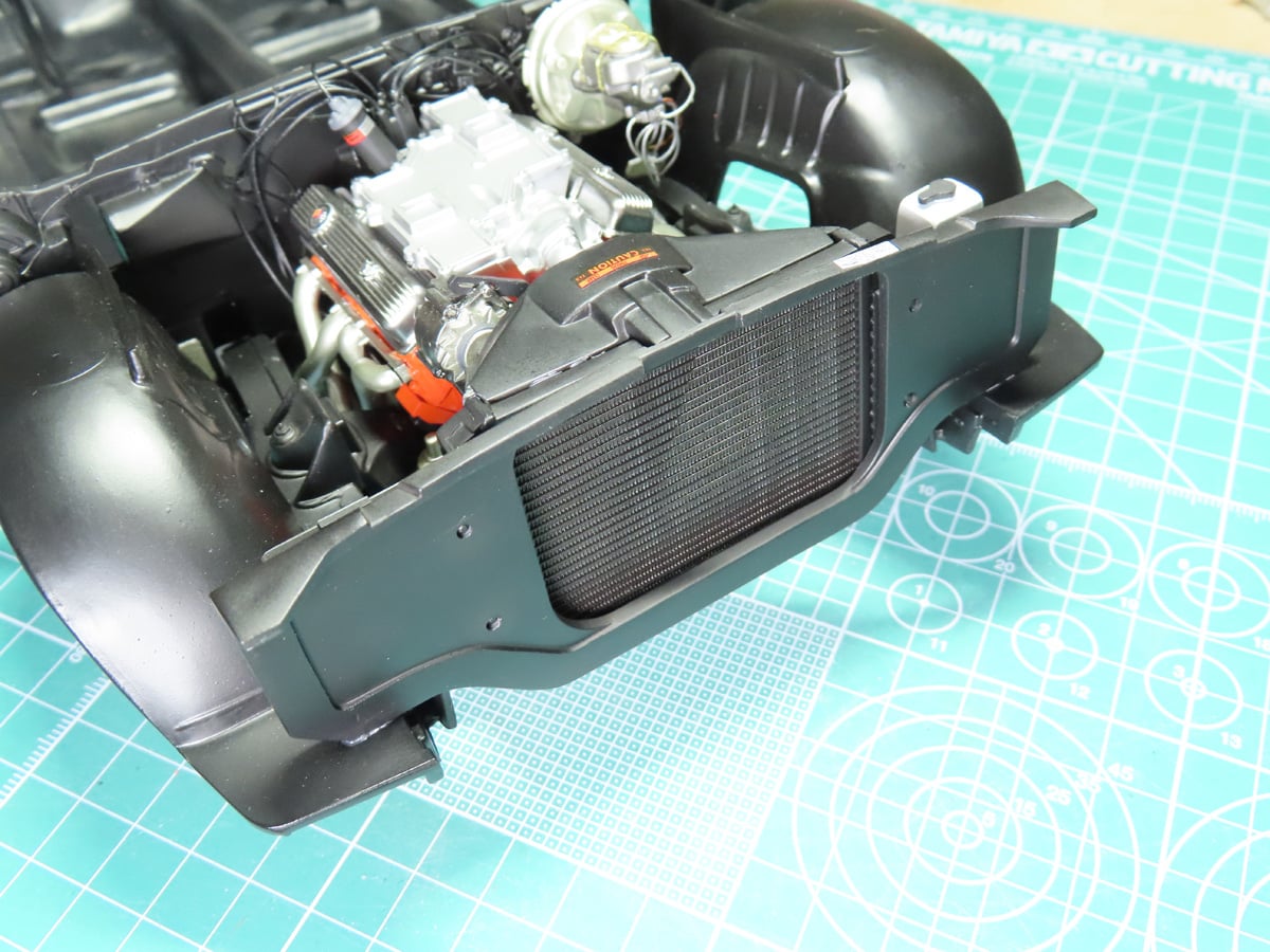
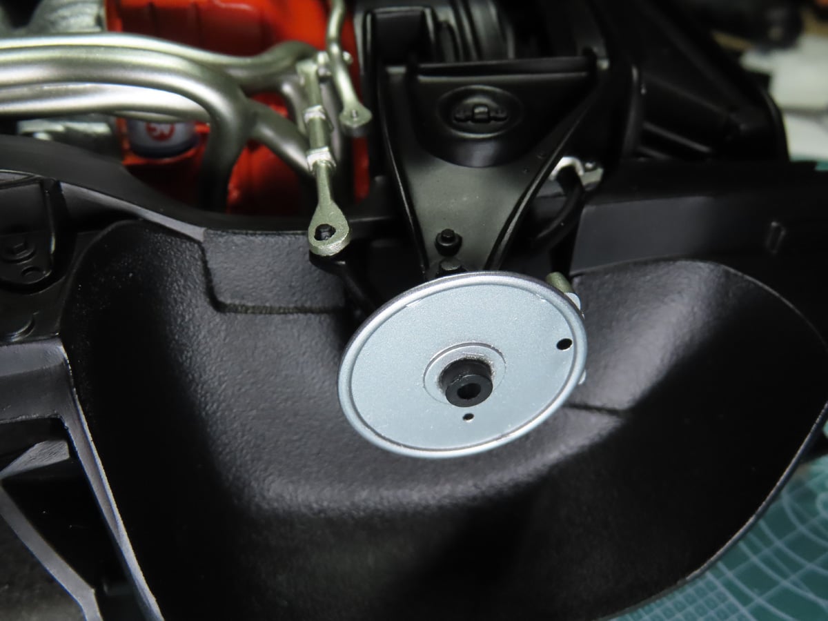
Flipping the car around now, I could also add on the radiator assembly. The part mostly “fits” into place, it’s not really as secure as I’d like to have, and it’s a part I’m going to have to be careful with when the body is placed over top.
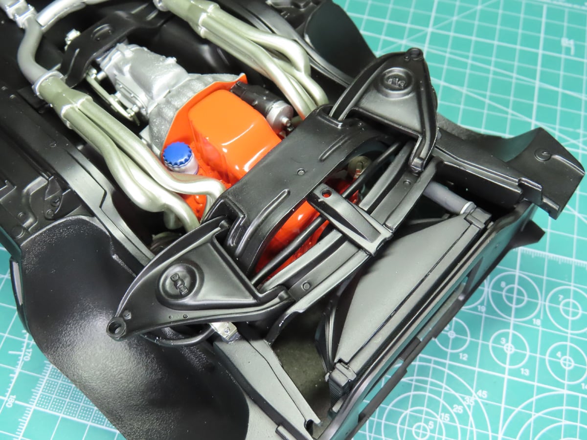
Flipping the car around again, I added the left and right control arms to the frame. These parts are quite critical as they need to take a lot of the weight from the model supporting the wheels. So take a bit of extra care to securely glue the arms in place.
The upper control arms caused me some confusion, as the instructions are quite vague on their placement. It turns out that Revell simply copied the old Monogram 1988 instructions instead of drawing newer and clearer ones.
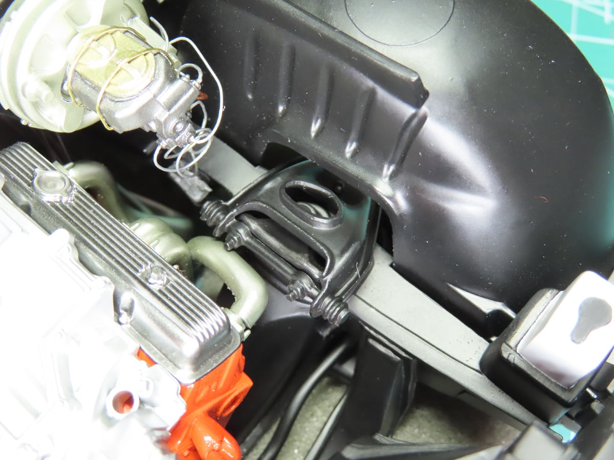
The Upper Control Arm needs to be glued to the inside of the engine and passes through the opening in the fender. I realize this is likely quite obvious to most of the car modelers out there, but for the rest of us, this is how the part fits in.
I added the disk brakes and the steering rod. At this stage, I realized that there was the control arms were a bit uneven, and though the parts were designed to angle the tires slightly, the parts didn’t move as freely as I wanted.
I carefully looked over the parts, and I’ve noticed that there is a slight warping. This was subtle and happened as I was adding parts to the frame. Though it’s minimal, it would be difficult to correct without a lot of sanding and tightly clamping down the parts. And sadly, at this stage in the build is something I can’t correct.
With this in mind, I decided to level out the parts so that the wheels would be straight when they were added, and I glued all of the parts in place.
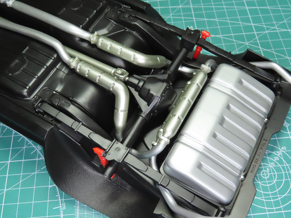
Moving to the back of the car, I added the rear axle, which is connected to a leaf spring suspension.
I ran into a fit issue with parts H31 and H32. The U-shaped opening on the underside wasn’t wide enough to reach the connection points on either side of the parts. At first glance, the parts look like an H-shape, but they slightly widen towards the rear of the car.
Using my hobby knife, I carefully carved out the plastic, and the parts fit with ease.
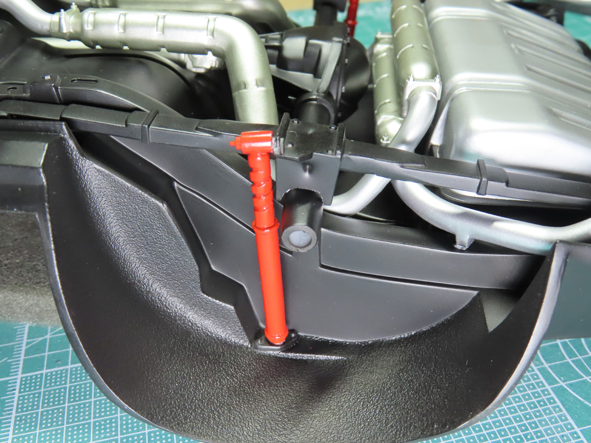
Lastly, I added the rear shock absorbers to the suspension. I read that the first and early versions of this Camaro had red shocks, and later versions were grey. I don’t know if this is truly accurate, but I like the idea of adding extra color to the model, and so I painted the shocks with Tamiya LP-50 Bright Red.
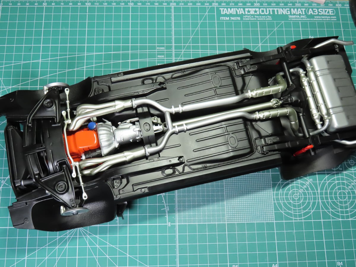
Looking at the completed chassis and engine bay, I noticed something I hadn’t seen before. And this was that the engine was slightly crooked. And for the life of me, I can’t understand what I did to allow this to happen. The engine fits into very loose brackets on either side. Brackets that I thought were parallel and even.
This slight offset is why the steering box didn’t fit properly in the last post. I believe that there are more warping issues with the parts that I wasn’t aware of at first inspection. I think I was too trusting of the kit, and moving forward, I need to double or triple-check the parts before they are installed.
I had a tougher time this week building the kit, as Revell is quite vague with the placement of some of the parts. I can now see why companies like Tamiya use screws to really fasten together some of the parts. And some clearer, redrawn instructions would have been very helpful at times.
That being said, I’m still really excited about how far we’ve come with this build. And looking at all of these parts come together has been very rewarding. And I’m also excited to leave this part of the car behind for a little while now, and get into painting and detailing the interior. There’s a lot to do in that section, and I’m eager to see that stage come together.
To be continued…
About the Author:
Jared Demes is a modeler from southern Alberta. He has been building models since he was 4 years old when his Dad first introduced him to the hobby. He has written for several magazines including, Fine Scale Modeler, Scale Aircraft Modeling, Phoenix Scale Models, and others. He has an interest in all modeling subjects, with a focus on WWII Japanese aircraft and Science Fiction.
Jared has won several IPMS awards for his modeling, and currently operates his YouTube channel rebelsatcloudnine, where he showcases model builds and product demonstrations.