
Tamiya North American F-51D Mustang
This is the eighth part of the Tamiya North American F-51D Mustang Korean War 1/32 Scale 60328 with RCAF Markings.
In this week’s post, we’ll be working on painting and detailing the landing gear bay. Like the tail wheel, this part of the build is designed to have removable parts to allow the model to be posed for flight.
With the last P-51 I built, I was asked by the client to add some extra wires to add further detail to this section. And there are quite a number of tubes and wires running through the gear bay of the P-51. It’s quite complicated on the real aircraft, but we’ll add a few here to help busy the interior up a bit more.
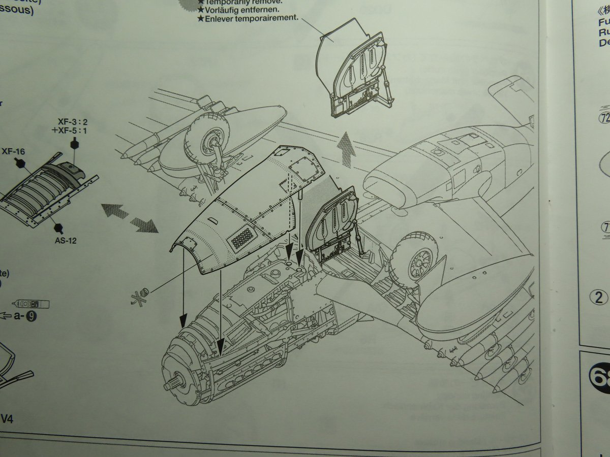
The challenge will be to add wires and not have them interfere with the rest of the model. As you can see here in the instructions, the center section with the gear doors is removed, and this gives you space to remove the lower cowling around the engine.
The wires also need to not interfere with the closed gear doors piece, as you will see later on, this part is quite blocky.
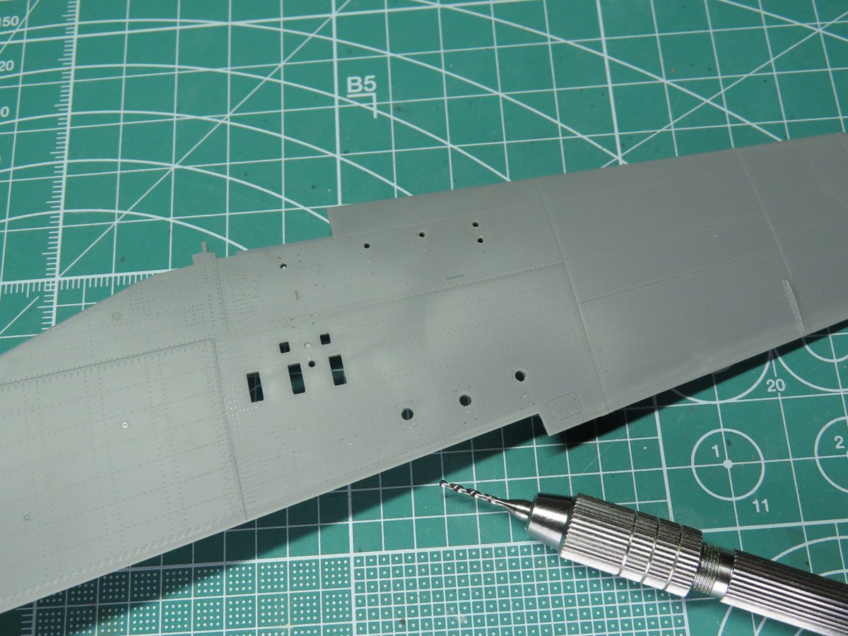
First, I needed to attend to a few of the details on the lower wing section. I needed to drill out the holes for the drop tank pylons, as well as the pylons for the rockets. Tamiya has intentionally staggered these holes so that the modeler won’t mix up their placement.
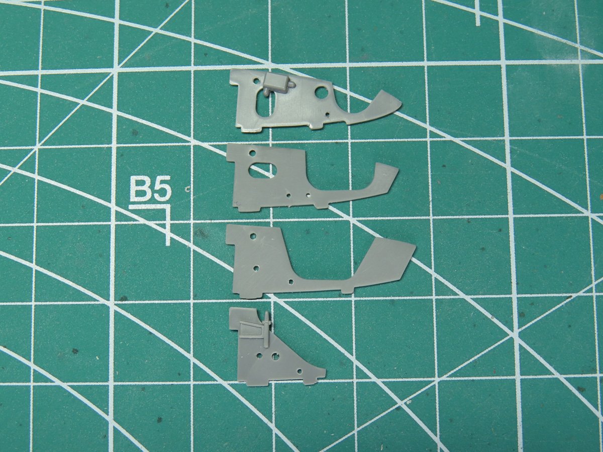
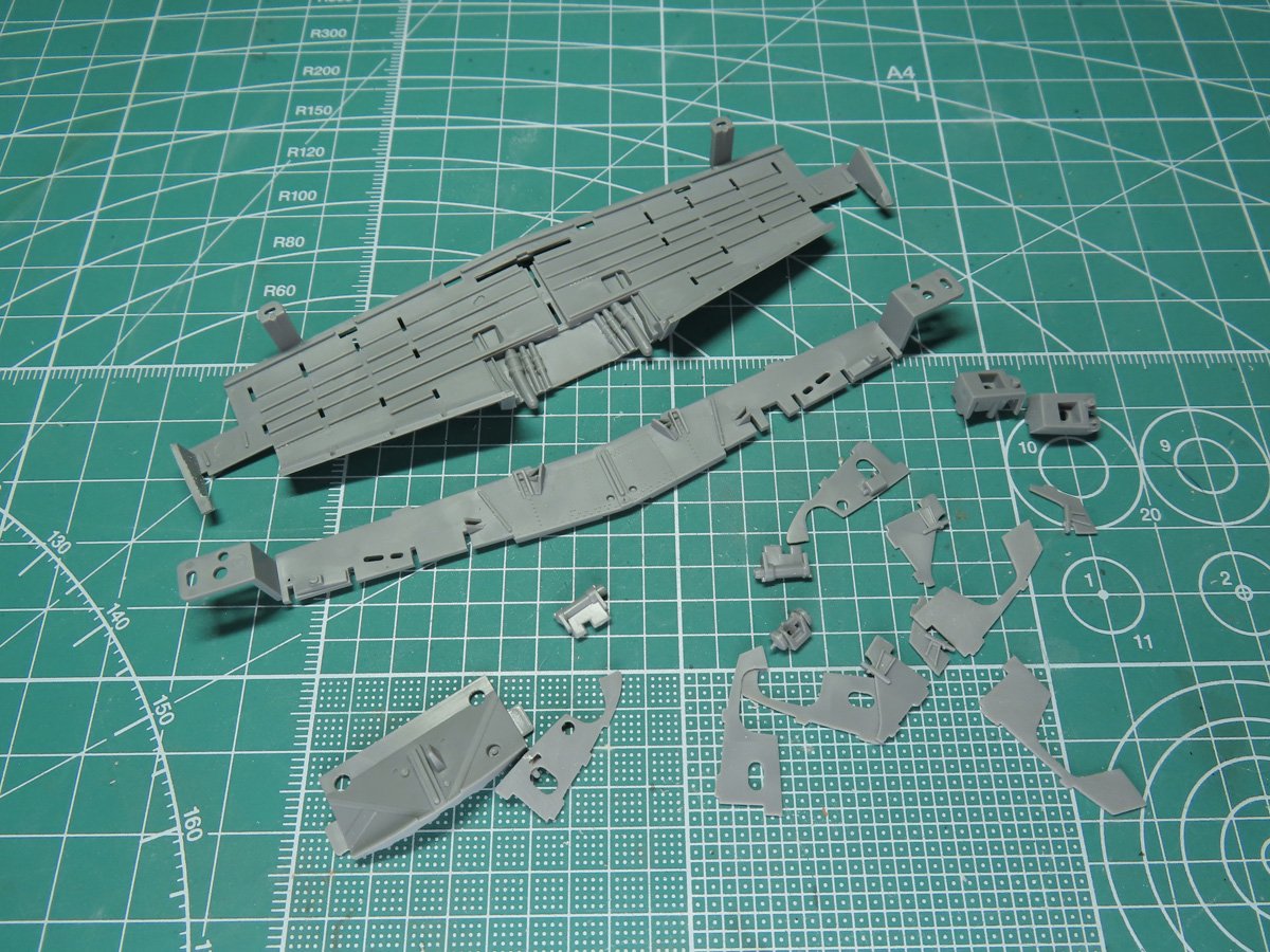
Here are each of the spars that will be placed into the bay. I went through and drilled holes in them where the wire was going to be threaded through. I’m going to be adding 4 wires, and 2 of these wires will be connected together, and for them I drilled a slightly larger hole.
These holes are mirrored on the other side as well.
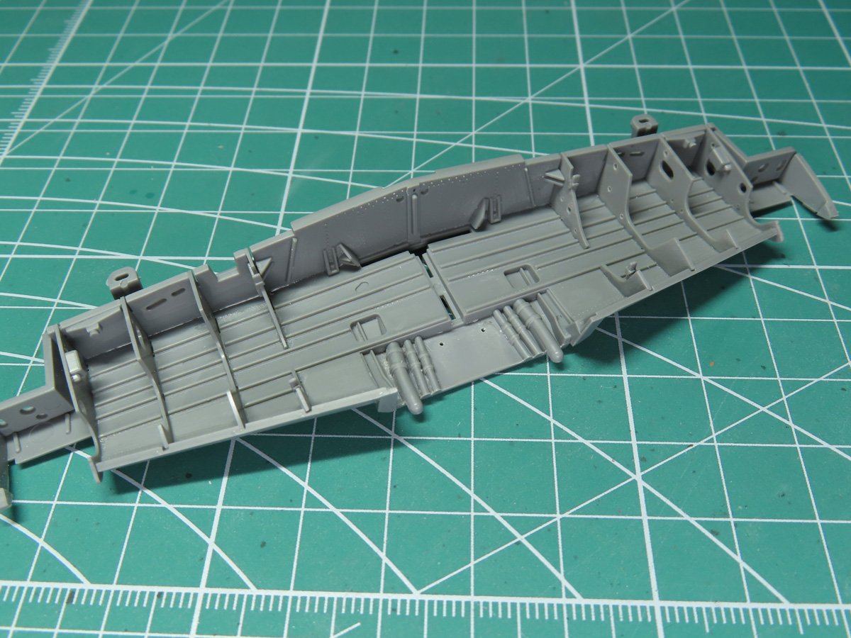
Two more holes were drilled out into the forward section of the floor between the piping. And once that was completed, I glued the backing and spars in place with some Mr Cement SP.
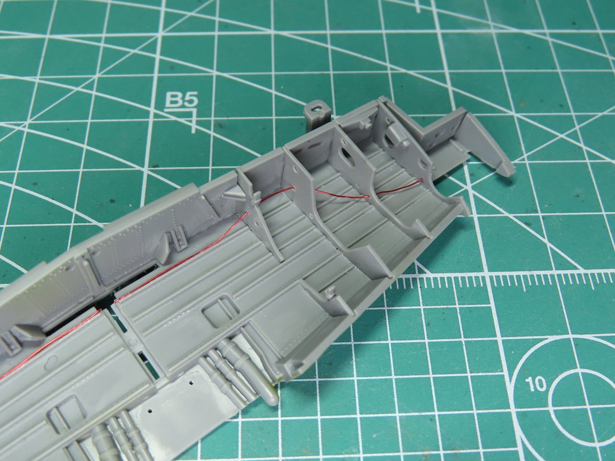
I decided to start by adding the wire to the back. I’m using K&S Engineering 0.20mm wire for this project, but you can use something thicker if you prefer, or you can even try using stretched sprue.
I glued the wire down with a small amount of BSI Cyanoacrylate CA super glue applied with a cocktail stick. Once that had dried, I carefully threaded the wire through the openings.
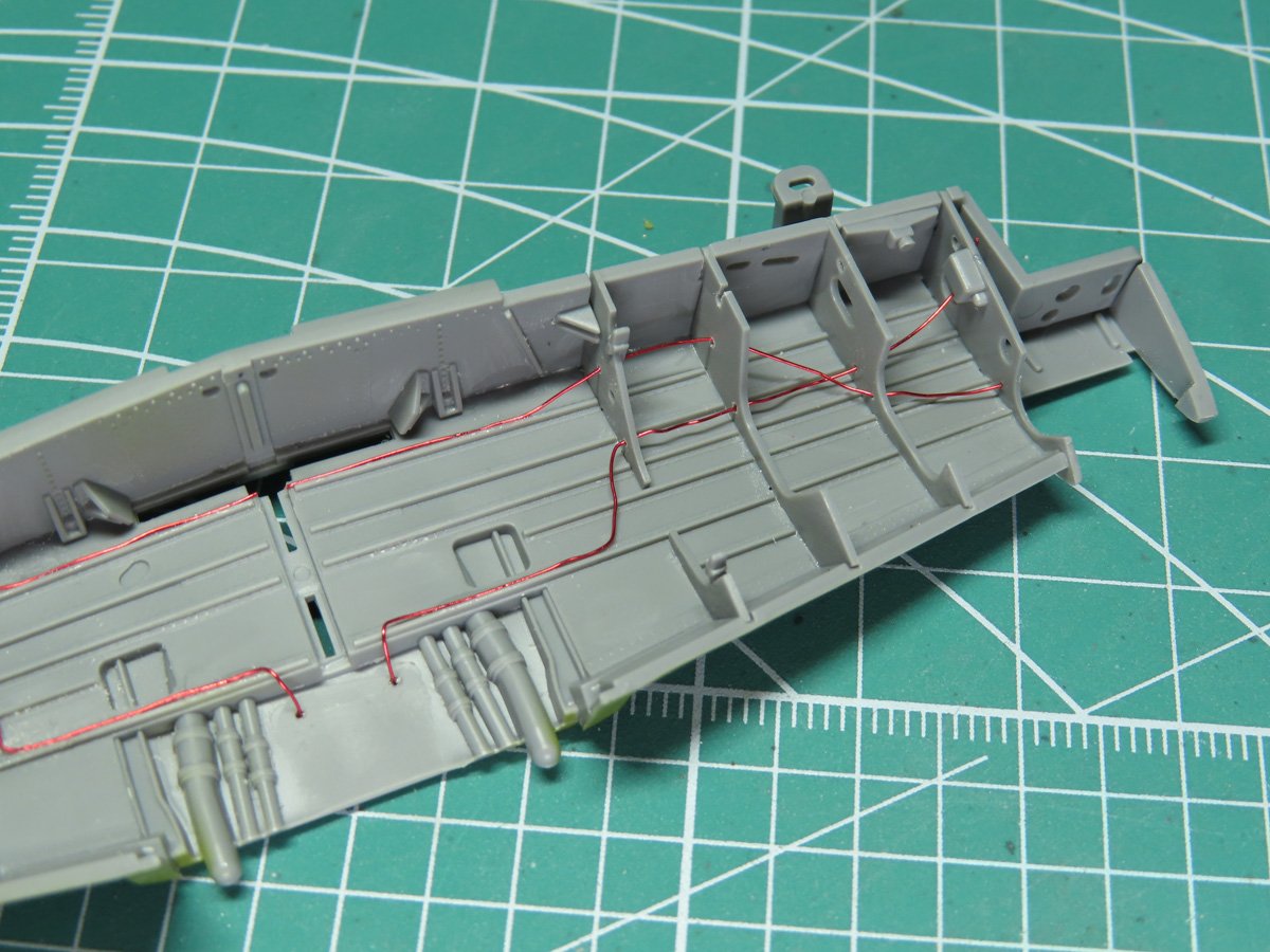
Next, I added the forward lower wire. As before, a thin amount of super glue was added to the frame, and the wire was carefully put in place. This time, I have the wire run through the opening in the last spar.
The last 2 wires are more difficult but very rewarding to see once they are installed. I first glued one of the wires to the flat of the bay. After that had dried, I carefully glued the second wire next to it. Using my Tamiya Pointed Tweezers, I was able to slowly thread the wires into the larger openings.
Once they were threaded through to the other side, I fixed them in place with more super glue.
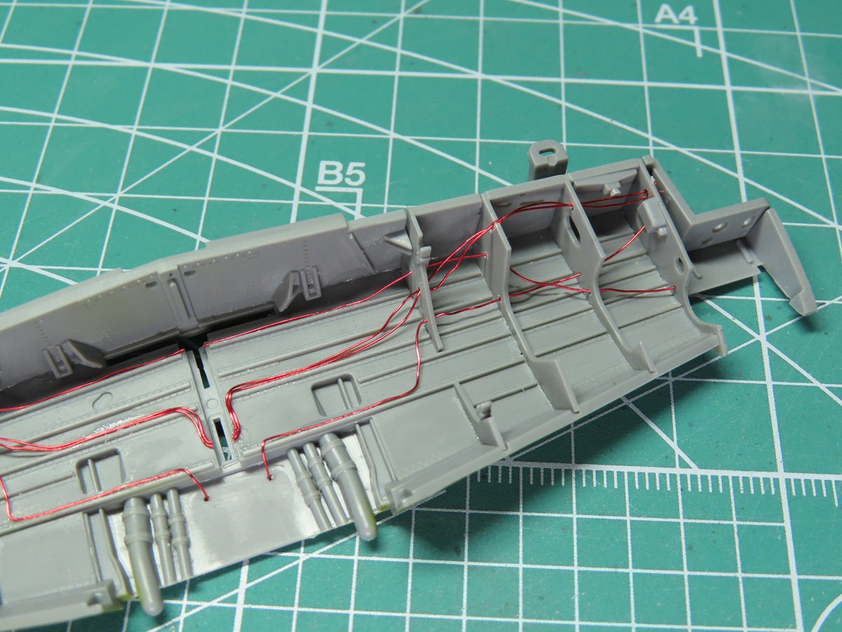
I then went back to the middle section and with the tweezers I carefully bent the wires into a curve, keeping them parallel to each other.
I trimmed out the excess wire with special sprue cutters that I have, which are designed to cut thin metals, very similar to cutters by Xuron 420T 90043 Coupe-carottes à cisaillement haute précision à tête inclinée. Always check with the manufacturer if your cutters can handle wire.
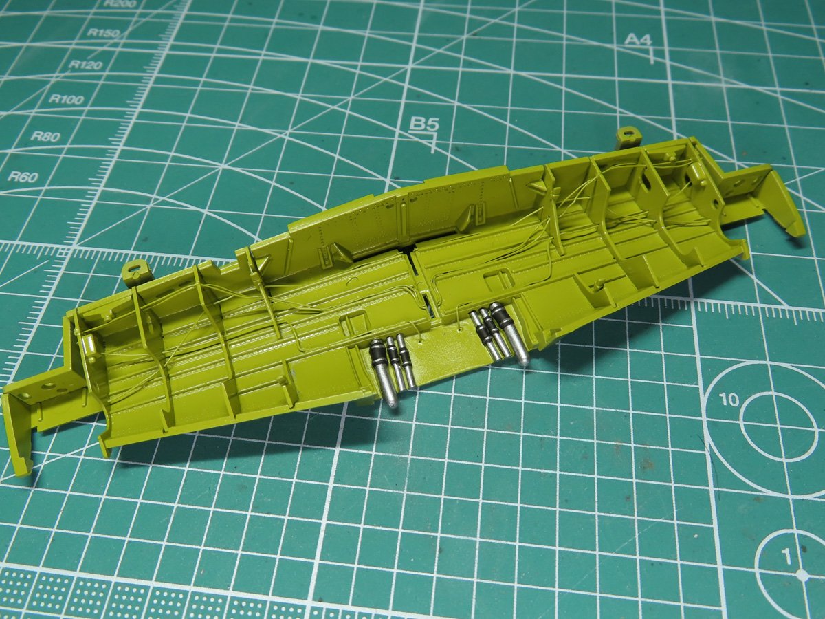
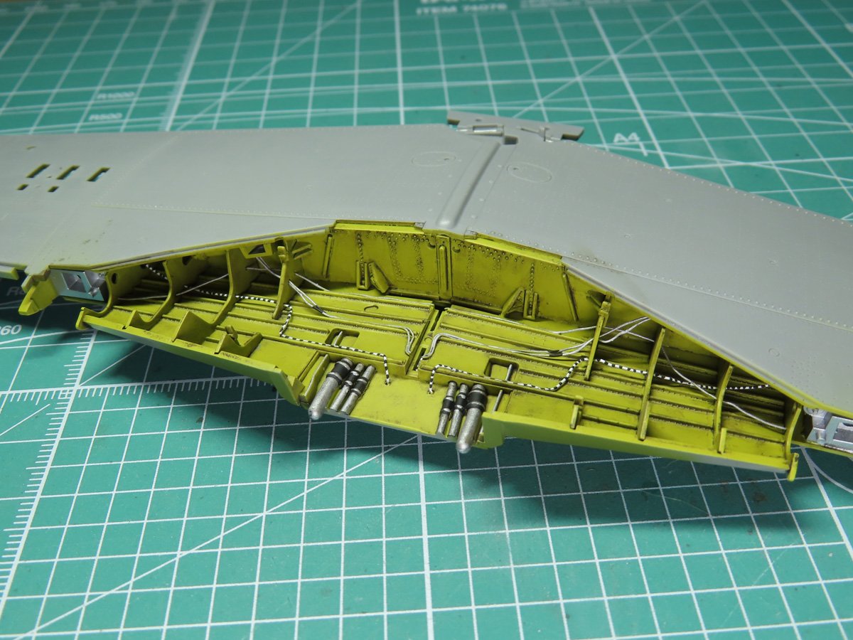
Now that the wires were in place, I painted the interior with Tamiya XF-4 Yellow Green. The paint was thinned with Mr Levelling Thinner, a specially designed Lacquer Thinner that had a retarder added to slow down the drying time and achieve a more even coat of paint.
However, in tighter places like this, the retarder prevents the paint from drying too quickly in the smaller corners. This is where the paint can swirl around and create a sandpaper effect.
I painted the tubes with Tamiya LP-72 Mica Silver, and this was a challenge as they are very tight and cramped in there. I wish that these were separate parts, as it would have made painting them easier.
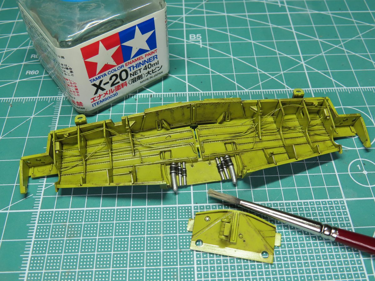
I gave the bay a wash with Tamiya Panel Line Accent Color Dark Brown. I left a bit more dirt on the back wall, with the intention that more dirt and debris would hit that area as the P-51 took off and taxied around the runway.
To remove the wash, I used a wider, stiffer brush and some Tamiya X-20 Enamel Thinner. The wash really did a great job highlighting the many details inside this section, especially all of the raised rivets.
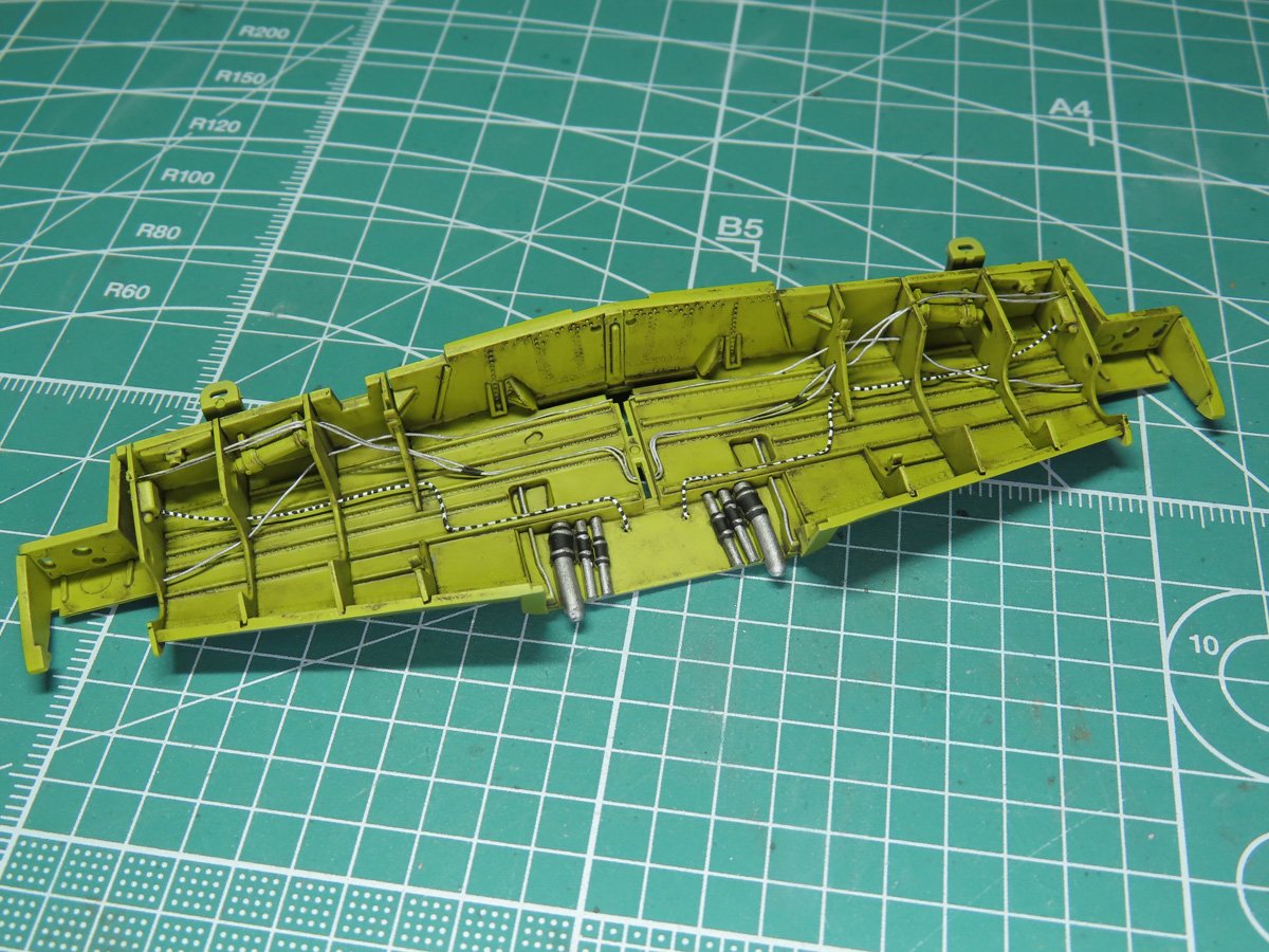
The wires towards the back were painted with Tamiya LP-72 Mica Silver. And the front was painted White and Black with AK Interactive (11001, 11029). Afterwards, I sprayed on a flat coat with Mr Color 182 Flat Clear to seal everything in.
One thing I will note is not to worry about painting every side of the wires, as they will only be seen from one side.
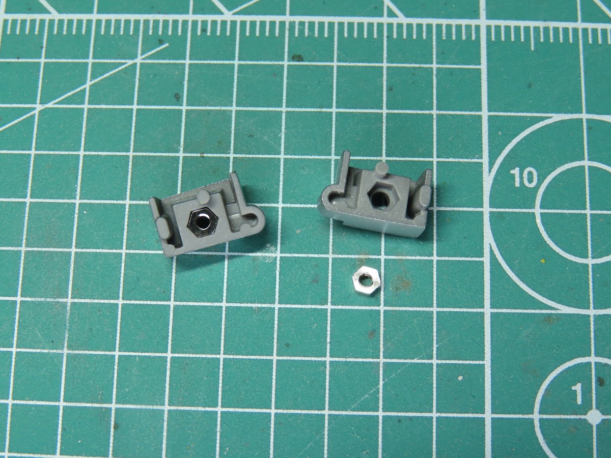
The last parts to be glued before the bay is cemented to the lower wings are the supports for the landing gear. A small nut needs to be placed to the backing, and then these parts were glued to the sides of the bay. I painted these with LP-72 Mica Silver.
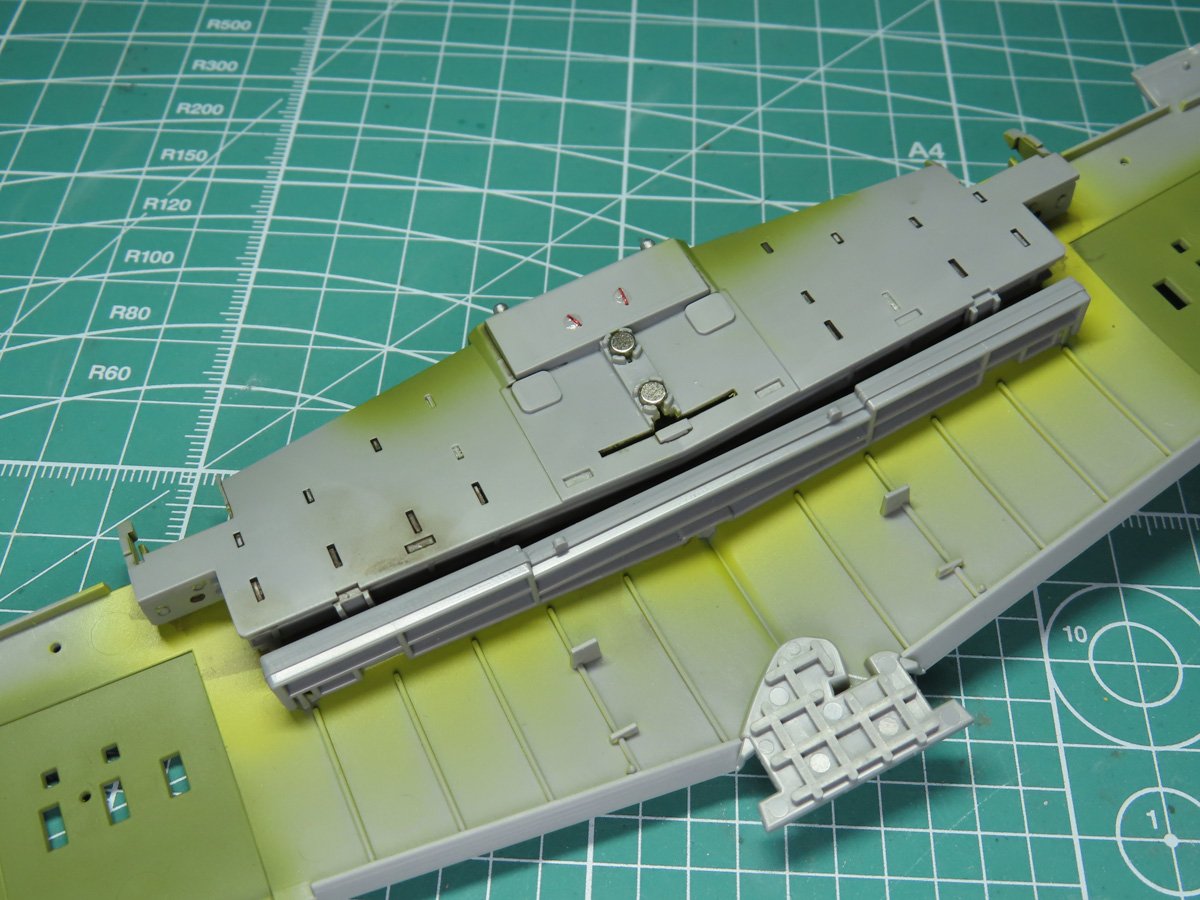
I carefully glued the landing gear bay to the edge of the wing section, and once this had dried, I added the wing support bar behind it.
2 magnets were glued to the top of the bay; these will help the center section doors stay in place. These magnets are very strong, so I suggest gluing one and allowing it to fully dry before gluing the next one.
The gear bay on the P-51 is a junction for many wires running through and around the aircraft. If you aren’t interested in the removable features, you might want to go all out and customize the rest of this section.
But if you are like me and like these functions, then hopefully this demonstration of adding in a few extra wires will help boost the details in your model.
I’m really pleased with how the wires look against the Zinc Chromate Yellow, and it will look even better once the doors and other details are added.
In the next post, we’ll be building the gun bays. You might have noticed the Zinc Chromate Green sections already painted on the inside of the wing in preparation for this step. I’ll show you how to magnetize those sections, and then we’ll be able to glue the wings together and add them to the fuselage.
To be continued…
About the Author:
Jared Demes is a modeler from southern Alberta. He has been building models since he was 4 years old when his Dad first introduced him to the hobby. He has written for several magazines including, Fine Scale Modeler, Scale Aircraft Modeling, Phoenix Scale Models, and others. He has an interest in all modeling subjects, with a focus on WWII Japanese aircraft and Science Fiction.
Jared has won several IPMS awards for his modeling, and currently operates his YouTube channel rebelsatcloudnine, where he showcases model builds and product demonstrations.