
Tamiya Lockheed Martin F-35A Lightning II 1/48 Scale Kit 61124 – Part 2
In this Sunward Hobbies article and review I’ll be continuing the build of the Tamiya F-35A Lightning II in 1/48 scale (item # 61124).
In this post I’ll be completing the cockpit section along with the nose wheel section. You’ll see the progress from Step 2 up to Step 16. In those are many tips on masking, making painting easier and plenty of other useful modelling advice.
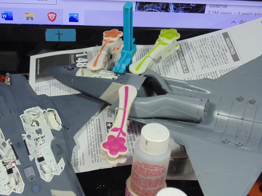
Be prepared for some fine hand painting. Since most of the detailed parts are Tamiya TS29 semi-gloss black you can spray it to save time. Semi-gloss is super nice to hand paint over, yet I still wet the brush tip to sharpen it.
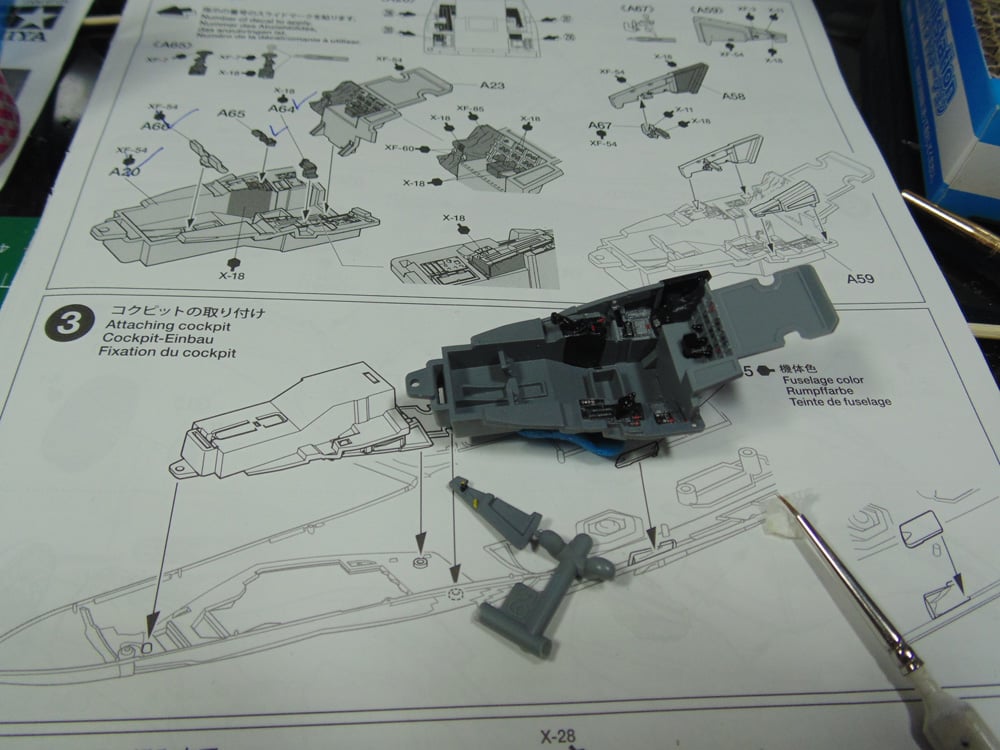
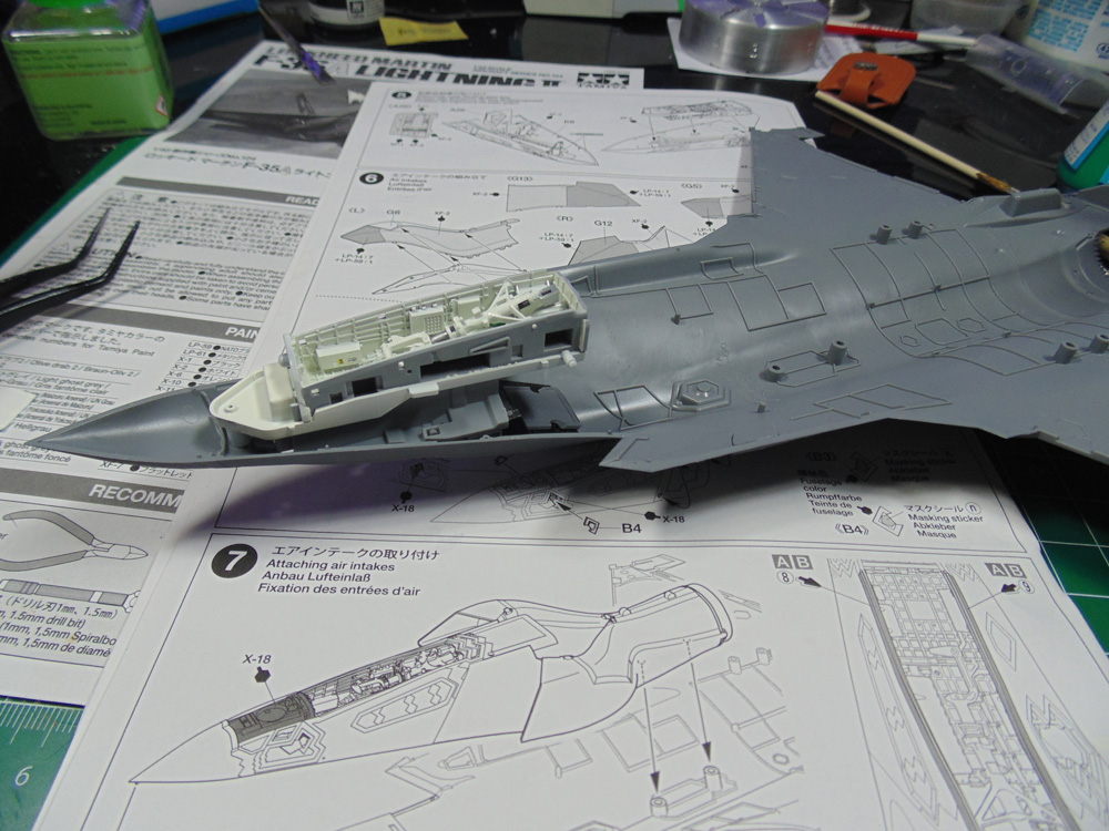
And here you can see the excellent amount of fine detailed parts Tamiya has engineered. This would be the time to decide if you’re going to add a panel line wash. After the seat and pilot go in there will be no room to manipulate the pigments.
Step 3 is straight forward. Be certain to remove all sprue gate nubs down to being flush. The tolerances on this kit are extremely tight.

Make sure you hold down the front connection point for a minute to help it out. Mine lifted and it was impossible to get a clamp in that tight spot. I opted to glue the front down and let it fully harden before gluing the rear points.
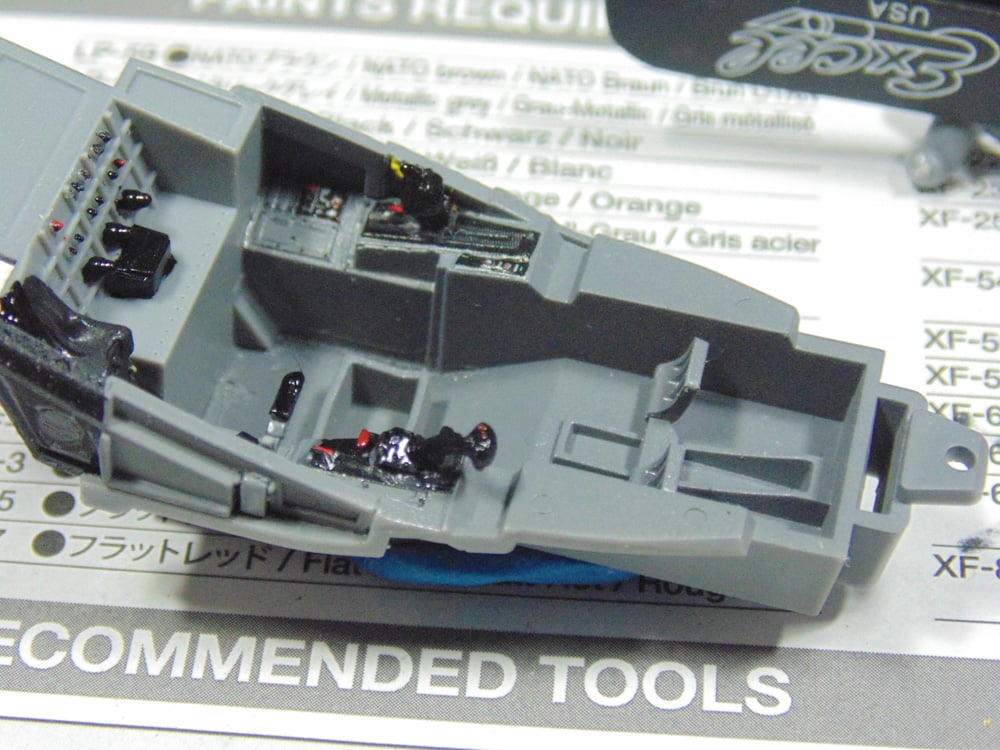
In Step 4 you’ll find some amazing detail. A sub-assembly filled with support beams, components and super sharp details. Tamiya decals are nice, but a hair on the thick side. Make sure you have a good decal fluid to help them conform. Sunward Hobbies have many brands of these setting solutions, so consult with the staff as to which is right.
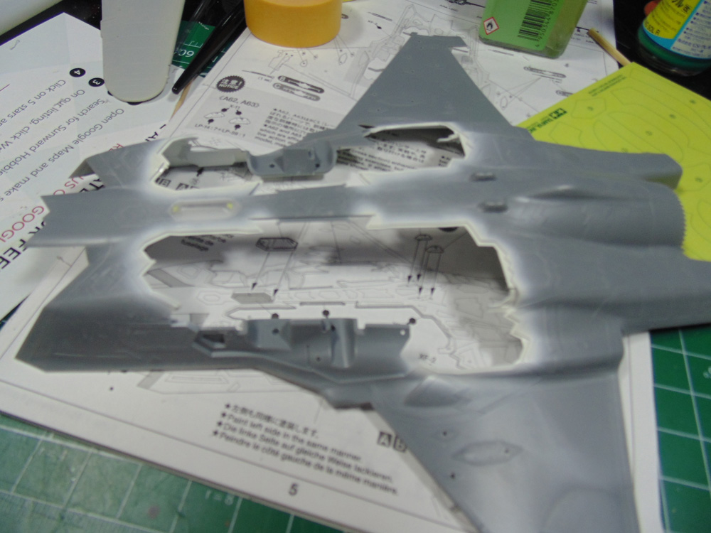
This section was time consuming, but well worth it for the end result. I did stray a little from the recommended Tamiya Acrylic XF-2 flat white for a Mr. Hobby Aqueous H316. The 316 has a slightly warmer look commonly used on F-18s. Due to this warmth it creates a shadow that looks close to being panel line washed.
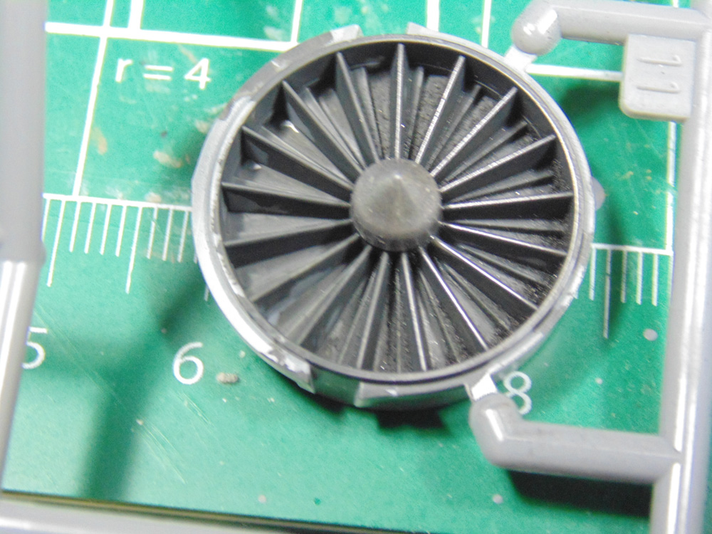
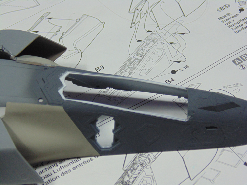
Step 6 shows the intake assembly. Not much to comment on here except that there is zero chance you’ll see the cone or fins on this part. I sprayed, chromed and even metalized the fins, only to discover that a tiny camera inserted was the only way to see the work.
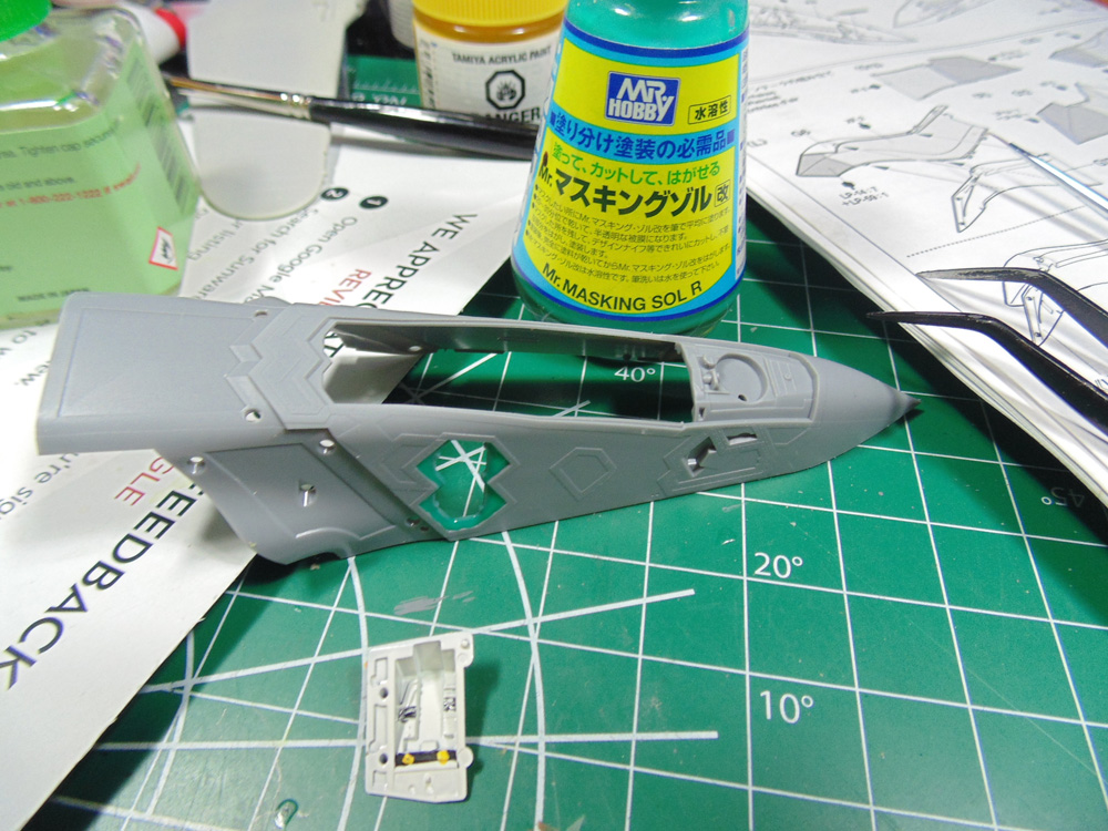
Next, I put some Masking fluid on the tips of the opening that need to be white. I don’t want the paint layer build up. Also, don’t attach the intakes to the nose part until after it is sprayed the fuselage colour, saves you masking it off.
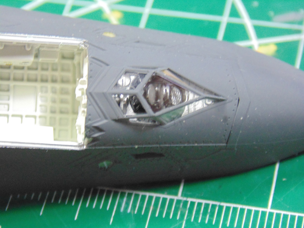
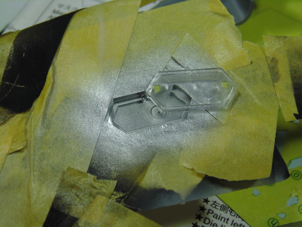
Now I’m going to leap ahead to get everything needed for the sensor to be completed. This way there will be a smoother paint transition. It’s easy to see the area under the sensors is sprayed when the masks come off.
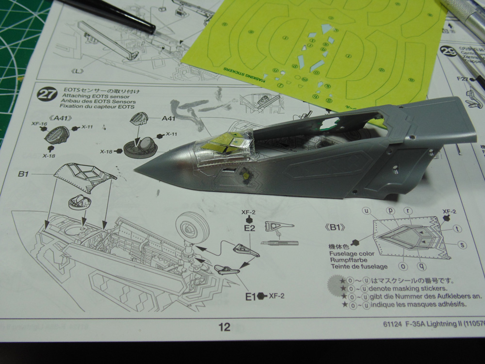
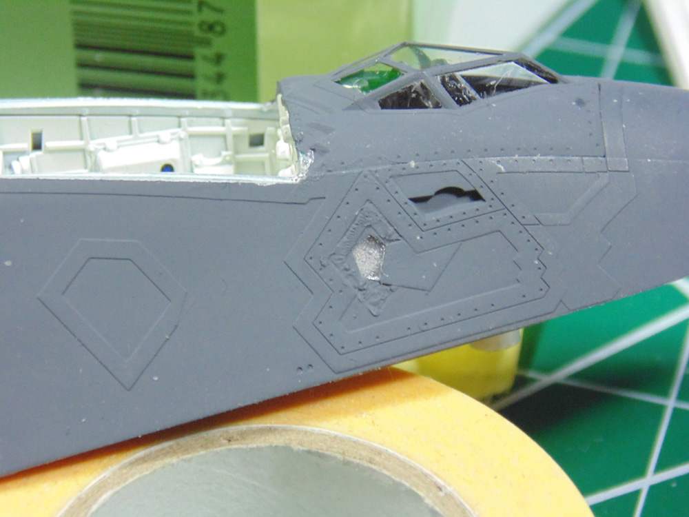
Before the base colour was sprayed, I painted the white trim then liquid masked it off. Just some easy touch-ups to take care of. Note the intakes can now be attached. The fit is glorious!!!
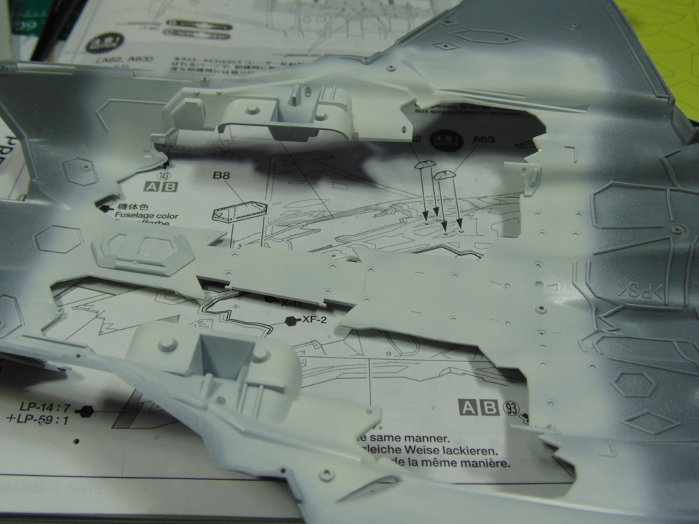
Here, you can really see the difference in white tones. It’s a personal thing for sure. Again, just a few touch-ups to look after.
This kit is stuffed with interior detail and these sensors are a perfect example.
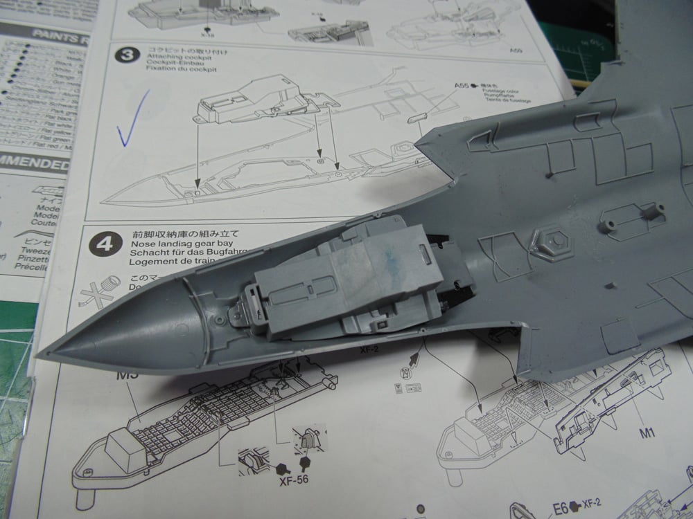
Step 7 has the upper and lower nose sections being connected. Make certain you test fit these subsections repeatedly until you’re confident of the best possible fit. Even with this done you may have to clamp things down.
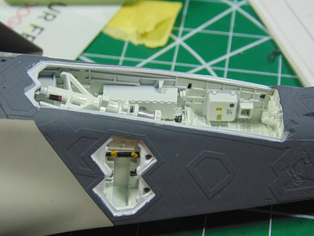
On the belly is another sensor array with masking stickers. Tape went down first on the bare plastic then AK Interactive aluminum AKI 479. Normally I give extreme metal colours an hour to dry, but any glue to enamel issues will be covered by the base coat dark grey.
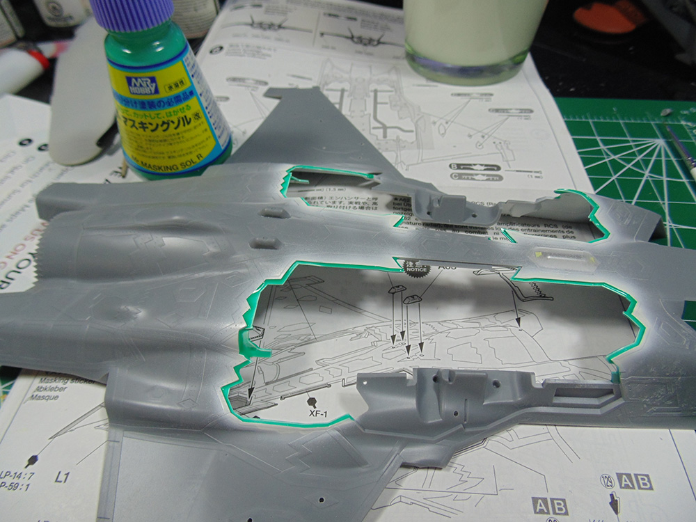
There are multiple angles along the edges of the bomb bays and landing gear doors. They have to be painted white. Stay close to the edges and begin with the outside.
There’s a very good chance when you spray the inside area that you’ll get all the angles painted. You begin with outside first to cut down on the amount of paint. This way you can use more paint on the inside to accomplish the task. Once dried you drill your holes for one of the three weapons load-outs. Tamiya did a splendid job making guide marks.
Using a super fine brush, I painted masking fluid to protect the edges. It would have been a nightmare to mask with tape. Tamiya Lacquer thinner 87077 will remove excess for the brush hairs. Don’t forget to do angled edges and a bit inside. Also, give Mr Hobby SOL R twenty minutes to set up. If you put a layer of paint on it right away it will slow the drying time considerably.
The intake leading edges obviously need attention. Make sure to de-tack the tape and do the inside as well. I leave a quarter of an inch overlap so I can pinch the two sides together for the best seal and less chance of under spray.
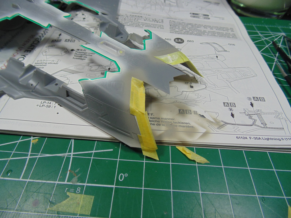
Just a few touch-ups to look after, but overall, it’s a nice clean look. When removing the masking fluid begin at a terminated end and always pull up at a 45degree, or less, angle. This will drastically reduce the chance of paint lifting and completes Step 8.
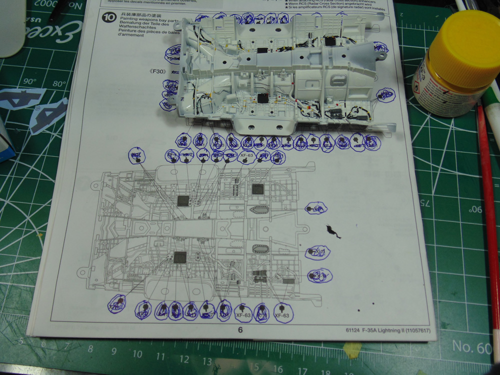
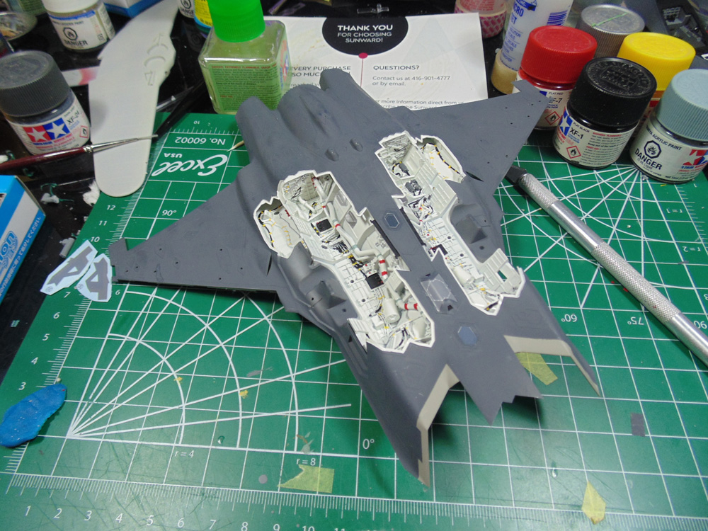
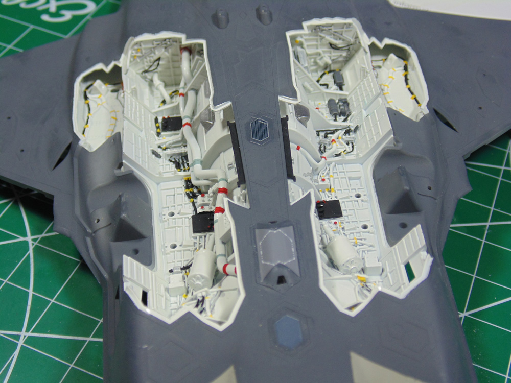
Step 9 has some belly decals for more sensors, but Step 10 is where the fun begins! The bomb bay is incredibly well detailed and an absolute shame to close it up. Circle all the identical colours then cross each off as you go. It’s a small tip, but sure helps considering the number of distractions I get. Use an ultra fine soft hair brush and hold it as close to the tip as you can for best control. Use magnifiers for ever greater accuracy.
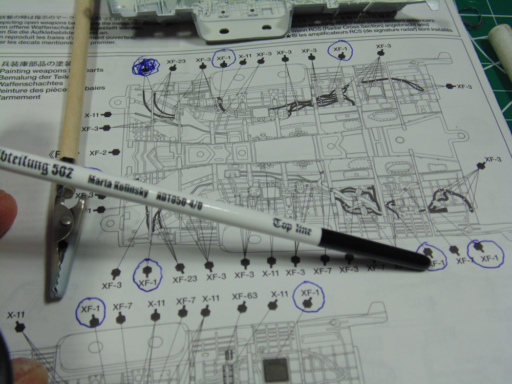
Be prepared to do some touch-ups here and there and have a bottle of IPA handy to wash your brush clean. Again, wet the tip to sharpen it after each cleaning. DO NOT use paint retarder in your colours for tasks like this. The paint will run and make an awful mess. Set aside a few hours for this delicate, yet worthwhile, work.
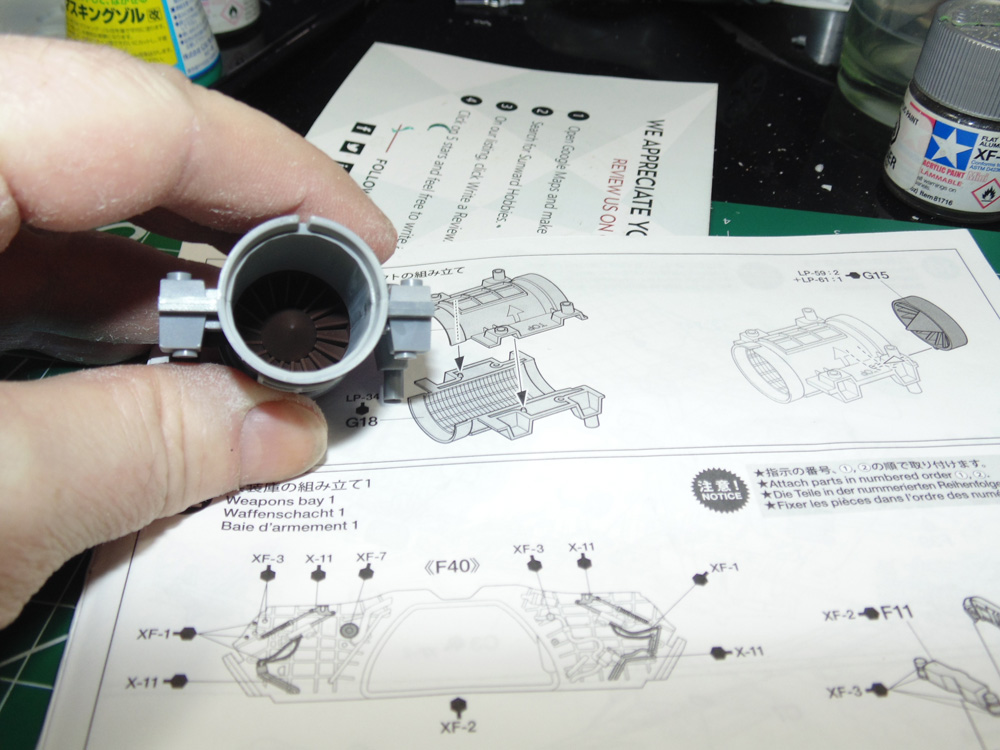
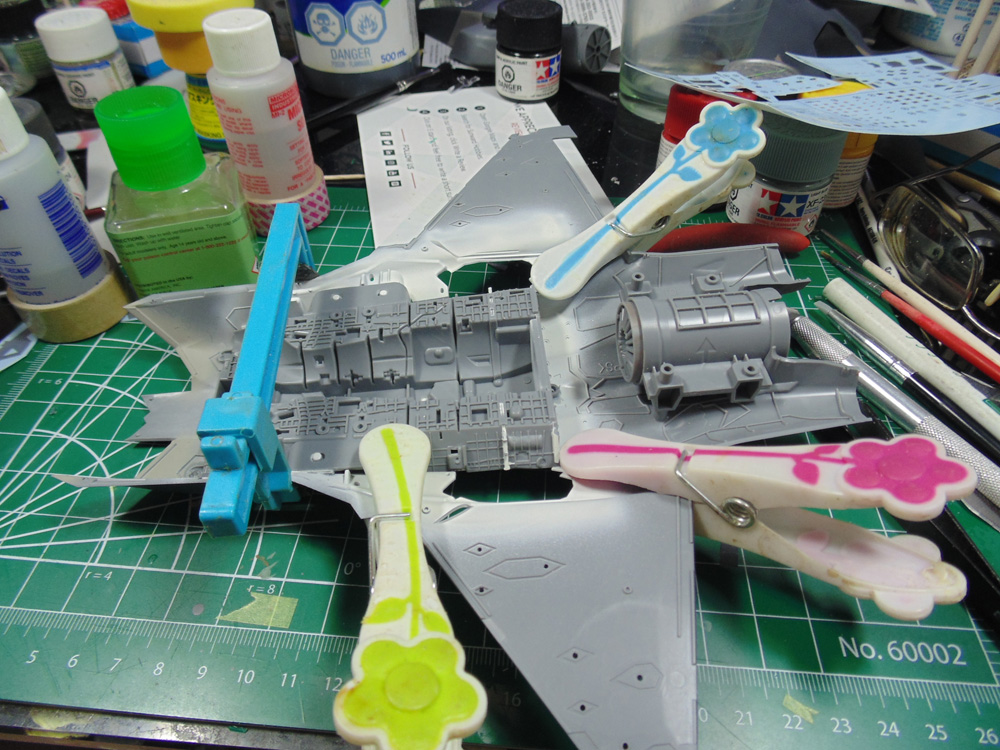
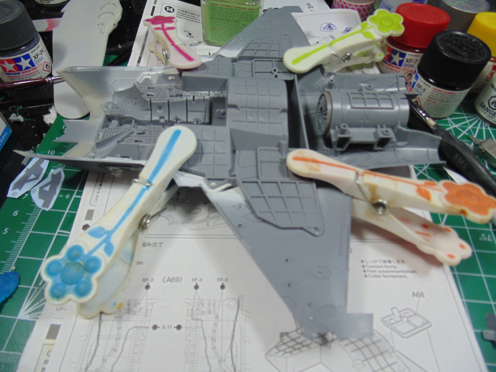
Step 11 is simply to paint and assemble the engine. All the parts are keyed to fit one way only, but Tamiya takes it a step further by adding arrows to show which side should go up.
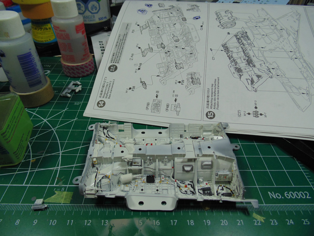
Steps 12, 13 and 14 display where the detail parts go and there are a lot of them!
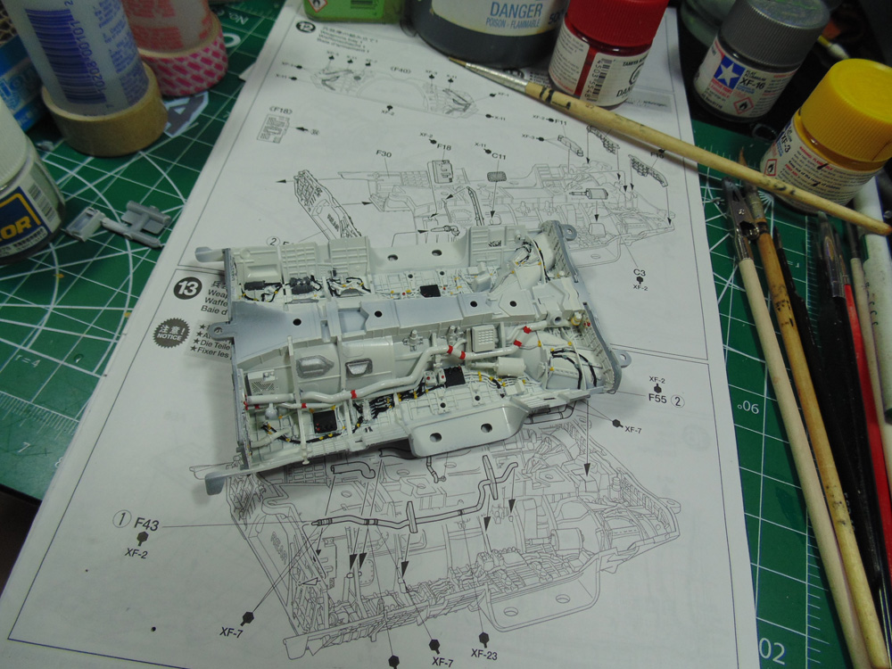
It looks daunting, but believe me the parts fall into place like a charm. Naturally, each add-on part was sprayed separately and fine painted prior to assembly.
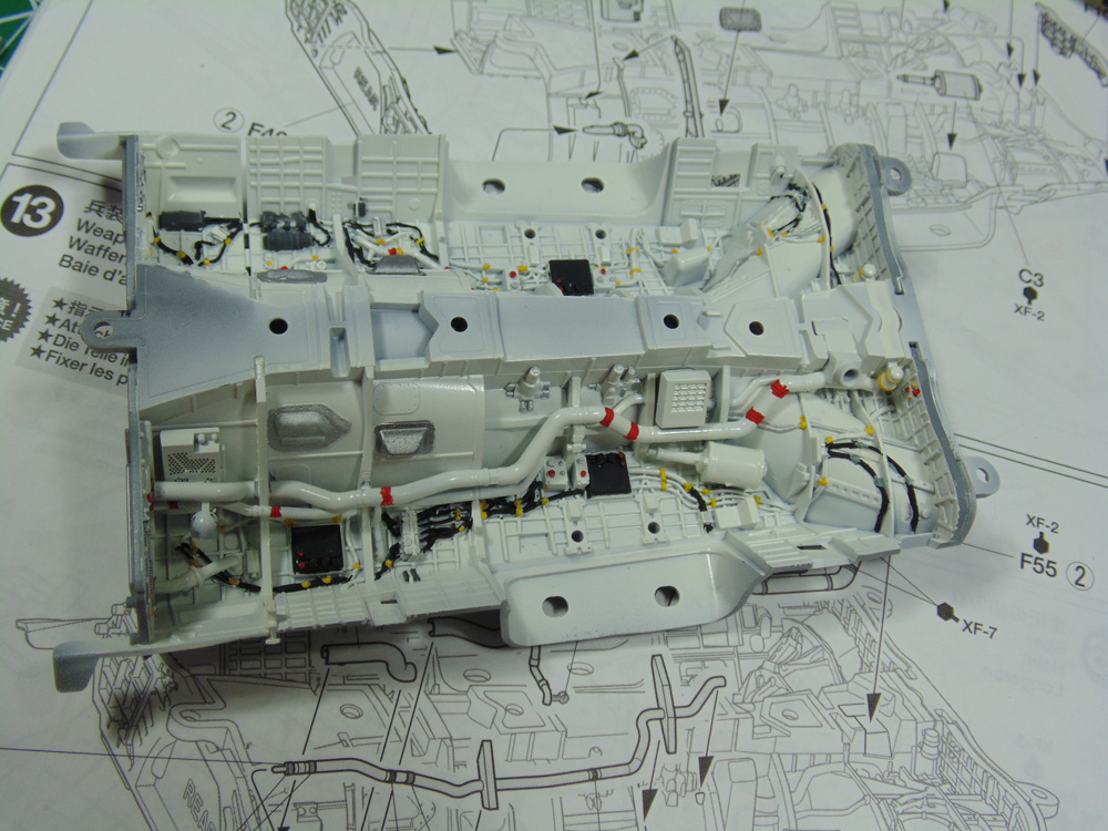
Now you see why I rave about this kit. With parts clean-up, spraying, adding painted details and assembly these three steps took roughly three and a half hours. But it sure is a thing of wonder.
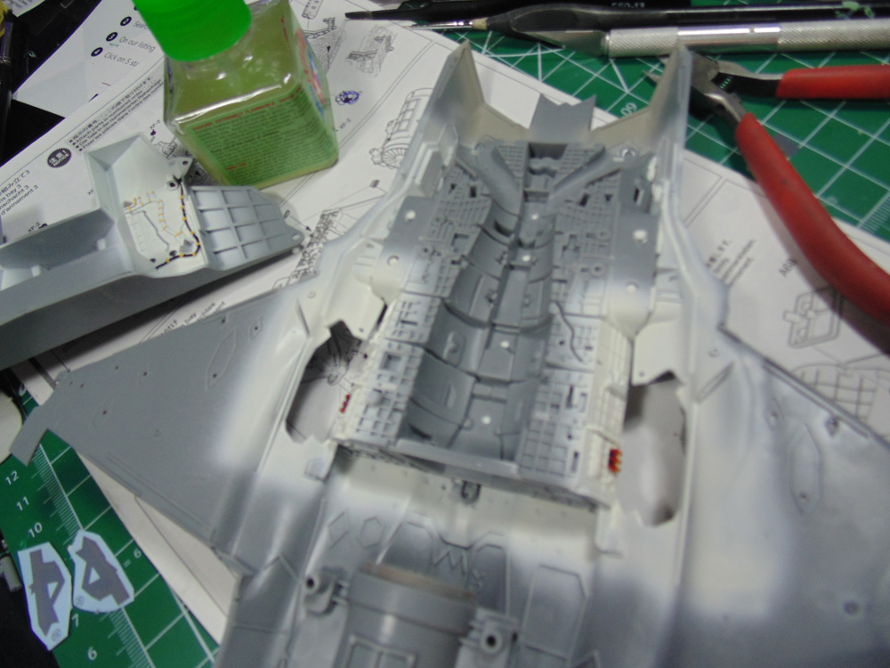
Get fit locations nailed down then use one spot to anchor it at one end. Let this set-up for ten minutes then go from side to side toward the other end, waiting a few minutes for each spot to dry a little. To make certain your glue weld is solid, use clamps.
The landing gear and wing spars have nicely added detail. Make sure you add plenty of glue to the strut supports, this is a very heavy model.
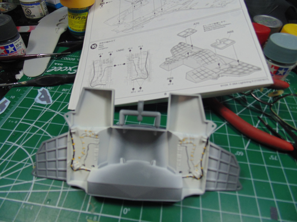
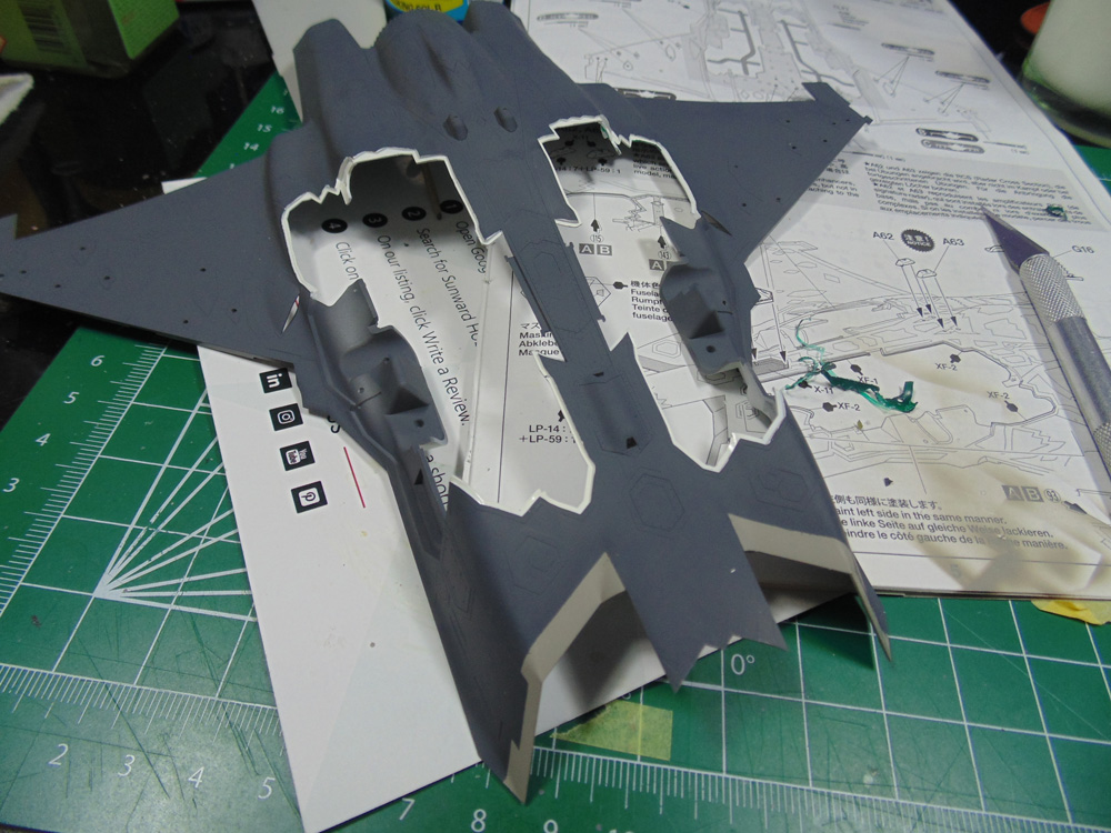
You’ll need to do some additional white painting not mentioned in the manual. Close up the holes from the inside so the white spray doesn’t get inside and muck up your interior details.
The fit here is really nice, but some clamps will speed up the drying time plus they will ensure the part stays put. Run your glue brush around all the edges of every contact point. Remember, the landing gear get installed in this part and will be holding up a lot of plastic.
This wraps up Part 2. You can see how impressive all the detail is. It was definitely time well spent.
While all the details are terrific, the star of the show goes to the bays.
If you have any questions about the products or methods used in this article, please feel free to ask the staff when you pick up or place your next order from Sunward Hobbies.
About the Author:
H.G. Barnes is a former voice-over artist and retired sales and marketing professional. He’s the author of two large volume science fiction adventure romance novels with many more in the works. For well over 40 years he’s been building scale model replicas and now does commission work for clients in Canada and the USA, plus completes projects for companies in Asia and Europe.
Currently H.G. is involved as an Associate Editor with KitMaker Network’s Online Magazine Channels.