
Tamiya 1/48 F4U-1D Corsair with Moto-Tug
This is the the second part of the Tamiya 1/48 F4U-1D Corsair with Moto-Tug 61085 build and review.
I was very fortunate while doing some research on this subject, to find an actual picture of 69 taking off of the USS Franklin. This picture is invaluable at the moment as it shows that most of the gloss is gone from flying and that this Corsair was a lot more beat up than I had expected. I initially thought that this was going to be a clean and glossy, or at least semi-gloss finish as is depicted on the box art.
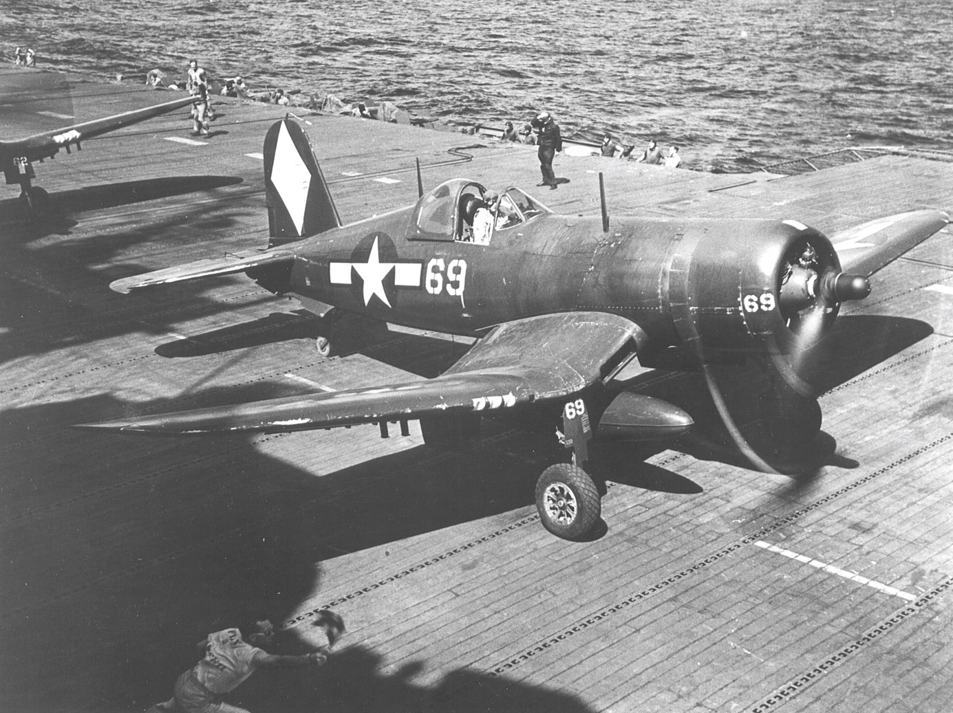
This is going to be a more fun and involved project as I can now plan for stages of weathering. One thing that really stood out to me was the pilot’s headrest. It’s a lot bigger than what is included with the Tamiya kit, and it sticks out quite a bit. I decided that I would replace this and sculpt a whole new headrest, this would be tricky as I already had the cockpit installed into the fuselage.
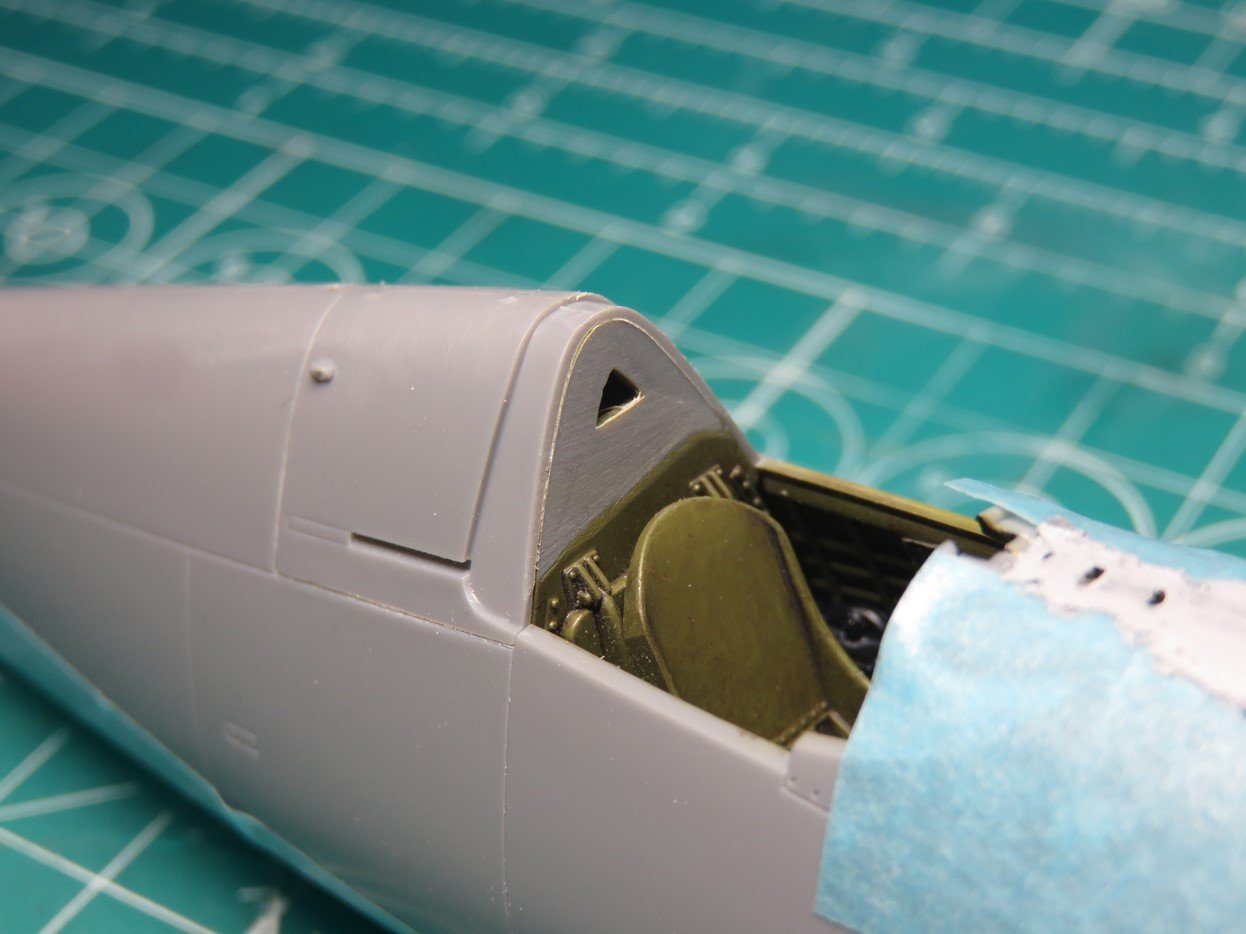
I used Vallejo sanding blocks (400 Grit) and carefully sanded away the old headrest. This was a slow process as I didn’t want to damage any of the lower details, and I didn’t want to accidentally sand away too much.
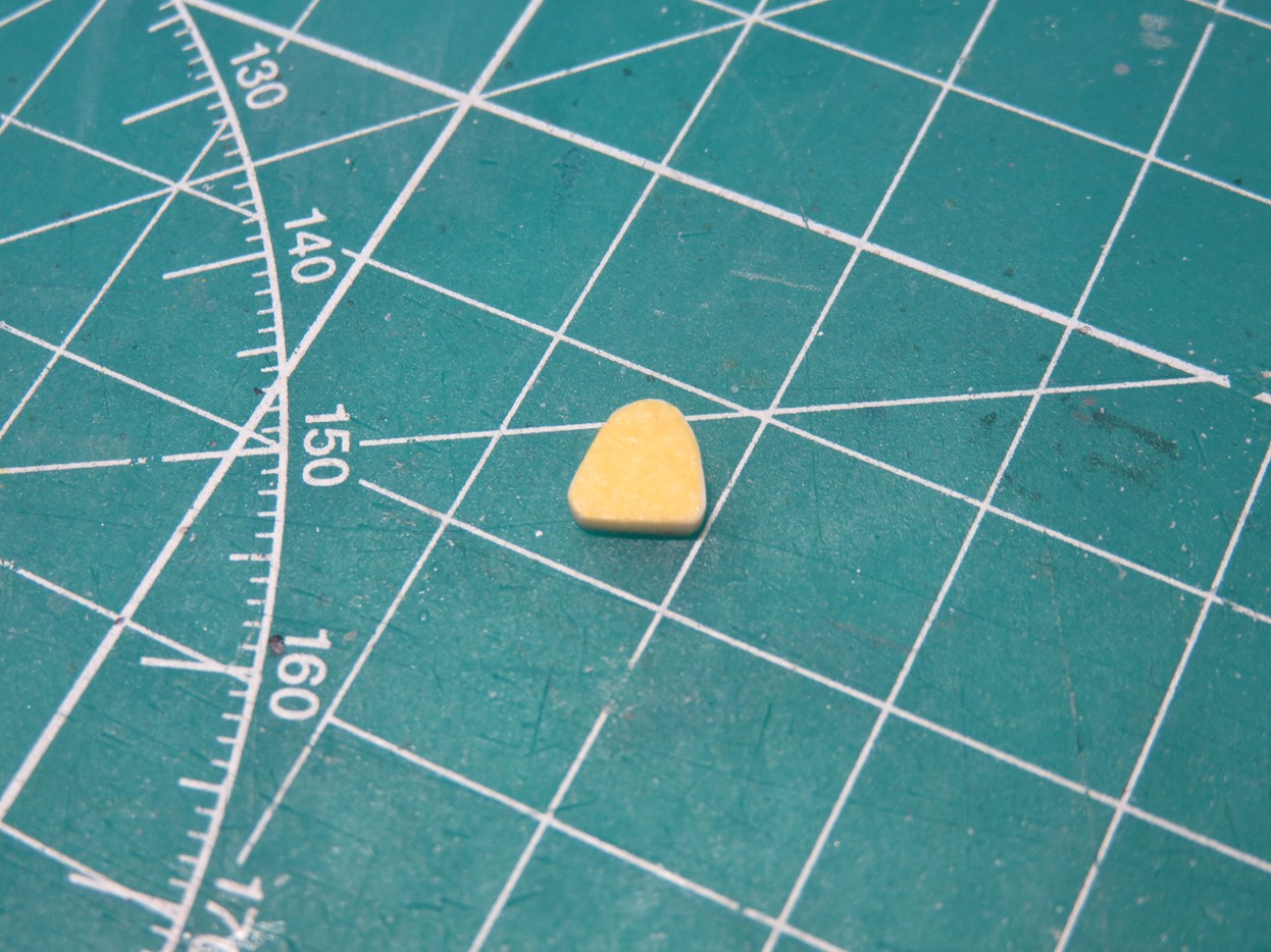
I started with a block of Evergreen styrene, and using Tamiya masking tape I made a small template in the size and shape of the headrest. This is similar to what I did when I made the new throttle controls. I then super glued with BSI CA Glue this piece to the back of some tape so that I could handle it while I sculpting, and so that I didn’t lose the part.
Next, I mixed up a small pea-sized batch of Milliput, a 2-part sculpting epoxy. I placed this over the styrene and carefully cut away the excess Milliput until I was left with this shape.
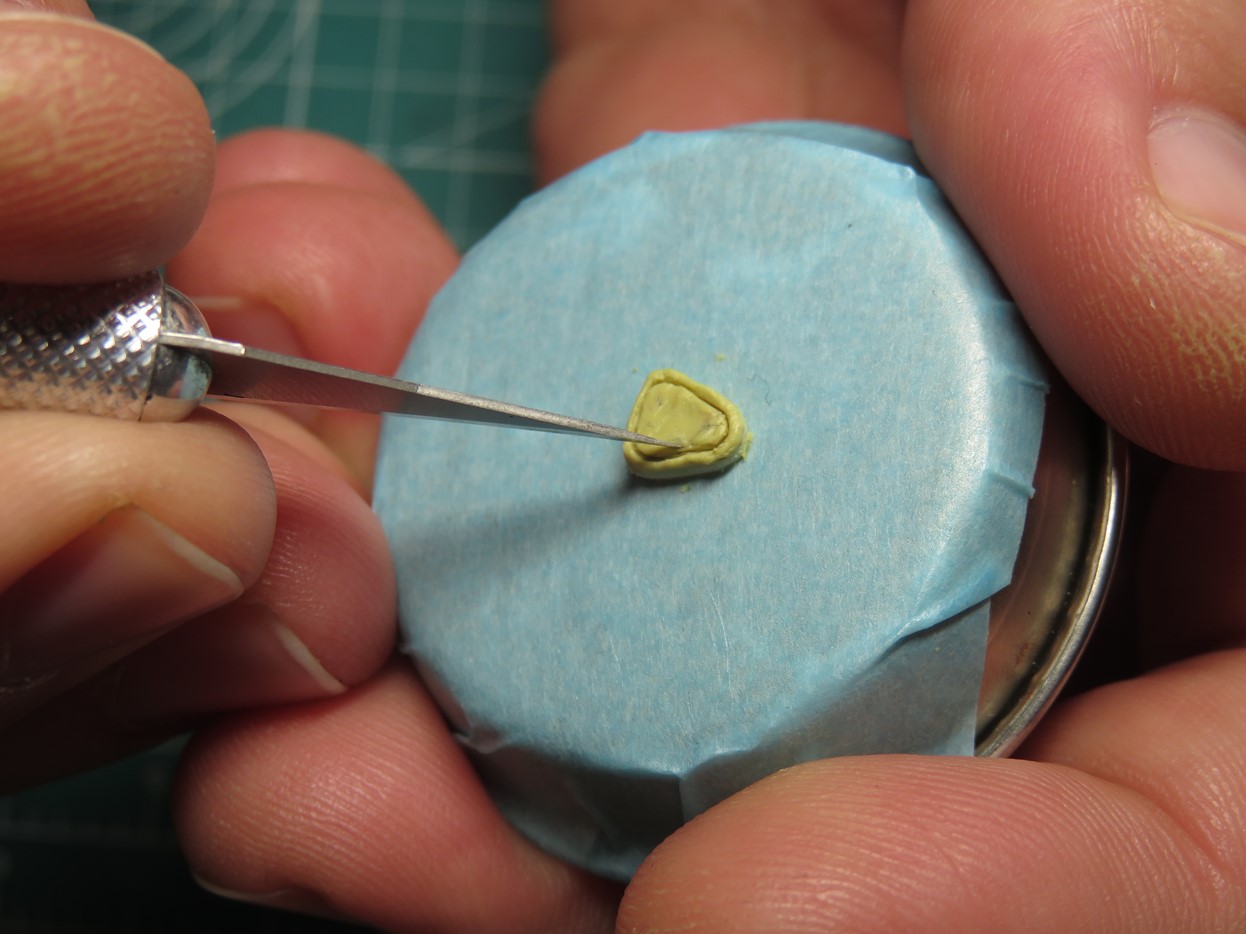
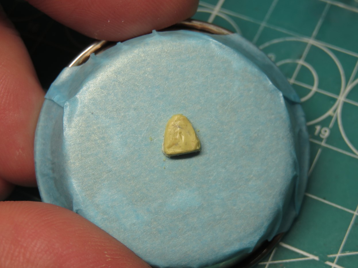
I wanted to add a thin line around the headrest that would replicate the 2 sections where the leather was stitched together. I’ve tried sculpting parts in the past and I’ve had trouble with the Milliput sticking to my tools. I watched an interview with the Perry brothers, famous miniature gaming sculptors.
They were asked by the interviewer how to stop the tools from sticking, and their advice was to use some hand lotion and apply a little bit to the end of the sculpting tool. This is one of those things that is so simple I wonder why I’ve never thought of it. And I can tell you from first-hand experience that this works, really well! I used my Excel hobby knife and a #11 blade to carefully cut the thin edge that I wanted.
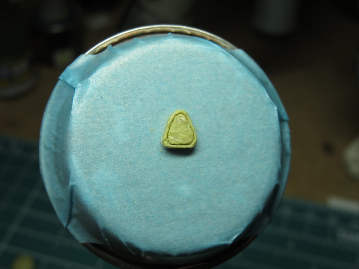
Lastly, I used a sculpting tool from The Army Painter to create a few creases in the center. I then left the Milliput to dry for several days before I removed the headrest from the tape and carefully sanded down and evened the edges.
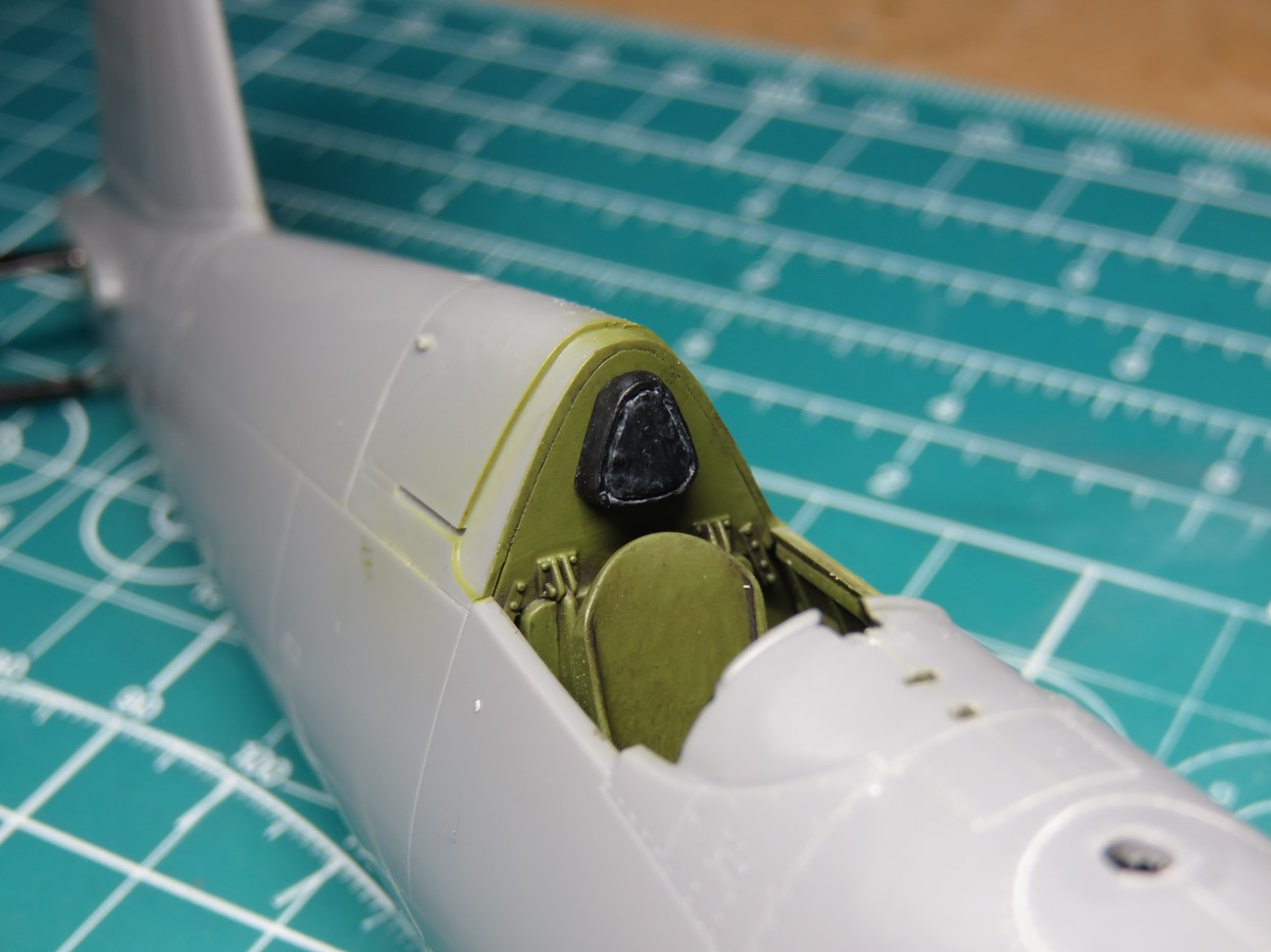
I repainted the cockpit green, and then I painted the headrest XF-1 Flat Black, and then used Tamiya Panel Line Accent Color Grey to highlight the recessed areas. Once this had all dried it was a simple process of gluing the headrest back into the cockpit and adding a flat coat to blend everything back together.
This was a challenging process, but I every time I try sculpting I find it to be a lot of fun. And I really like how this new headrest looks inside the cockpit.
This kit includes open and closed cowl flaps, unfortunately, these are a bit rough on the inside and don’t have any details. I decided that it could be a fun task to add some more details to this section. I started by sanding the inside as there are a few marks in there and I’ll need this space smooth for the styrene blocks that I’d be adding.
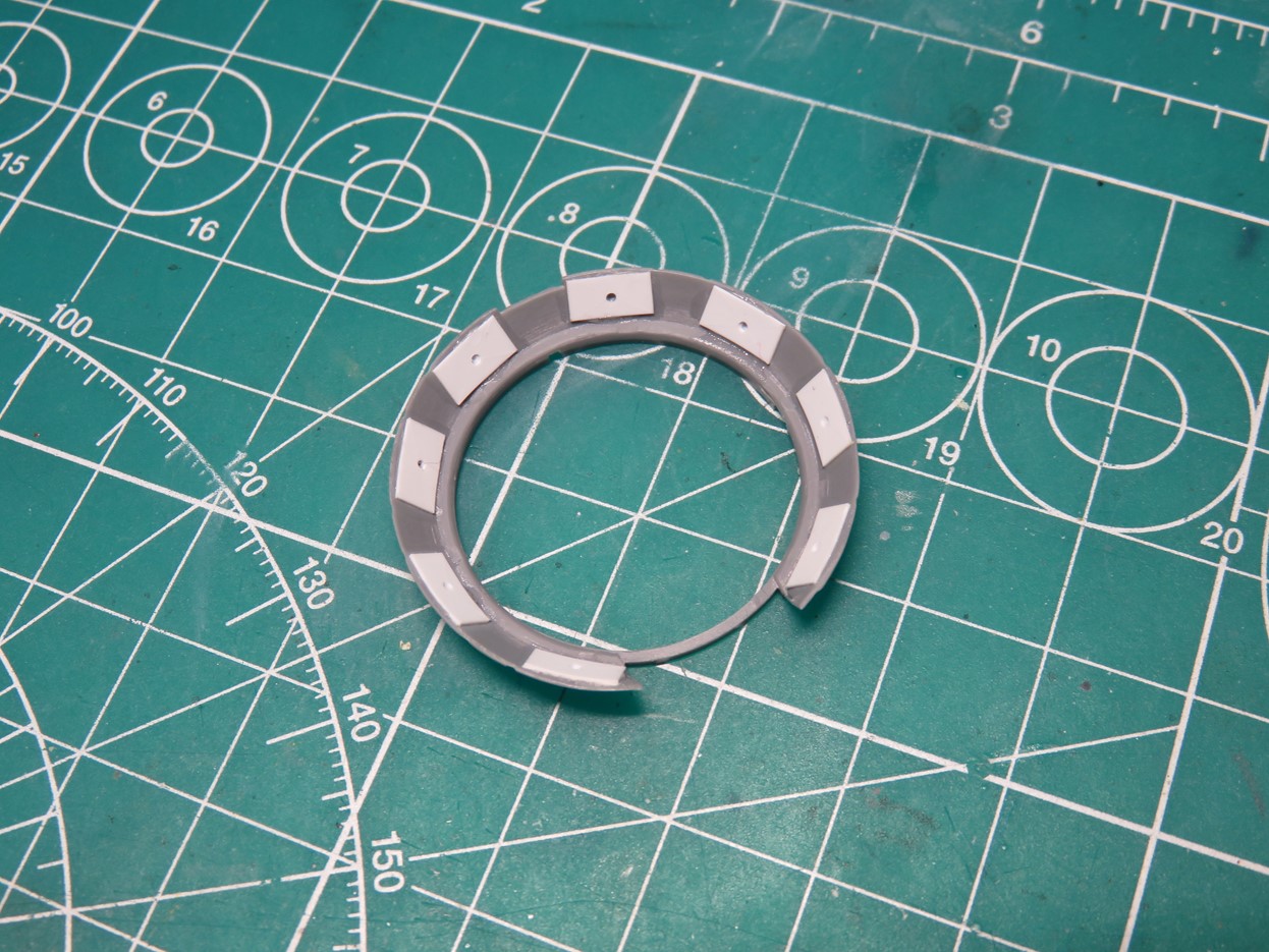
I added these blocks to all of the wider cowl flaps and drilled a small hole in the center. There are a lot of details on the real Corsair and because of the small scale, I’ll only be adding as much as I can build.
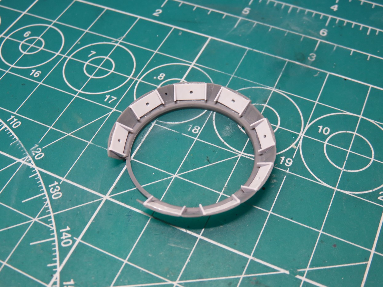
I then glued small triangles to each of the blocks, these were difficult to fix in place, so I used Mr Cement SP to fuse the parts together.
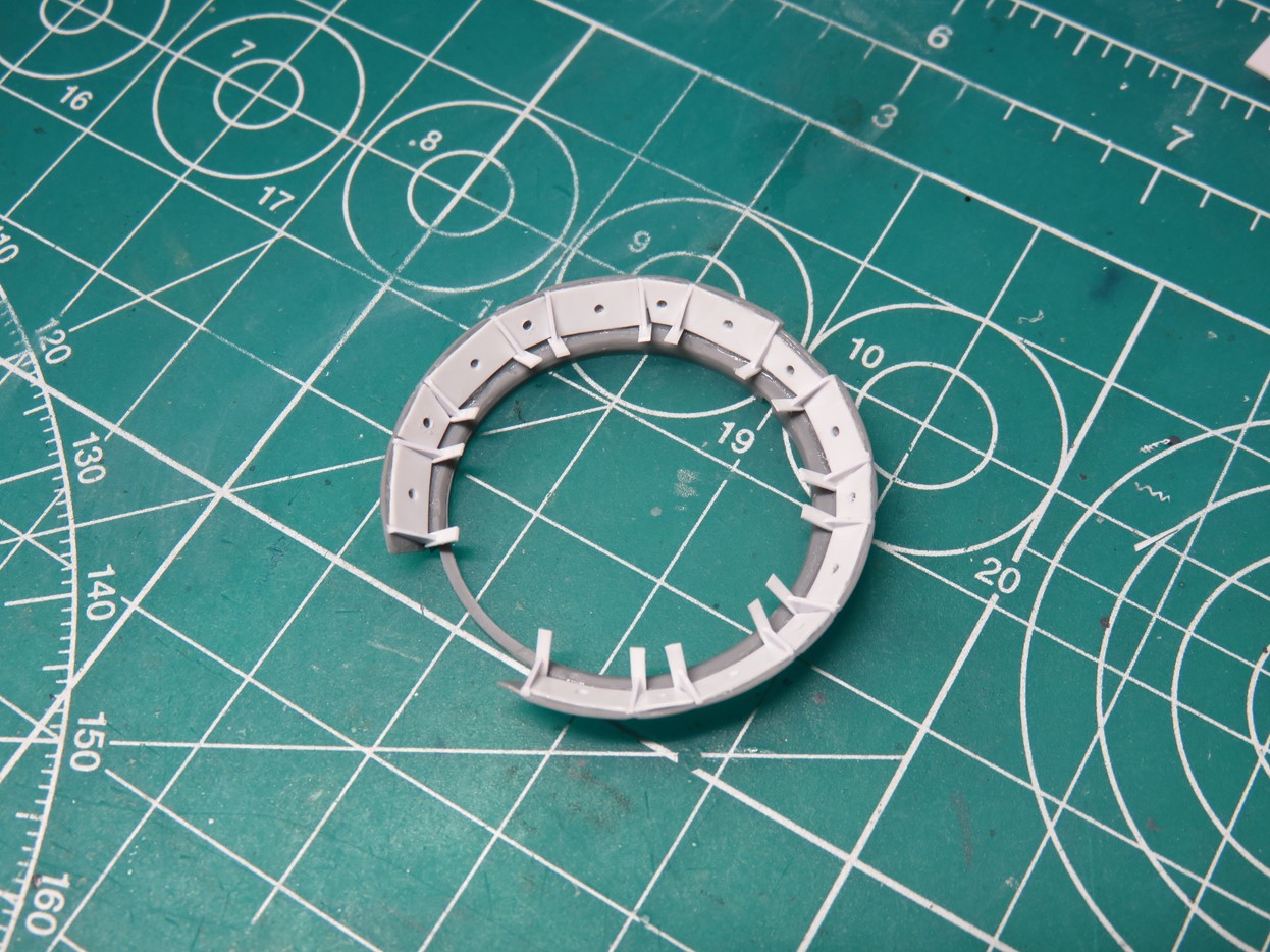
I filled in the remaining cowl flaps with smaller bits of styrene. Then I added longer plates to the ends of each of the triangles, these would be trimmed down once the glue dried, they were a lot easier to glue in at this size. This is where the springs would go that keep the cowl flaps open.
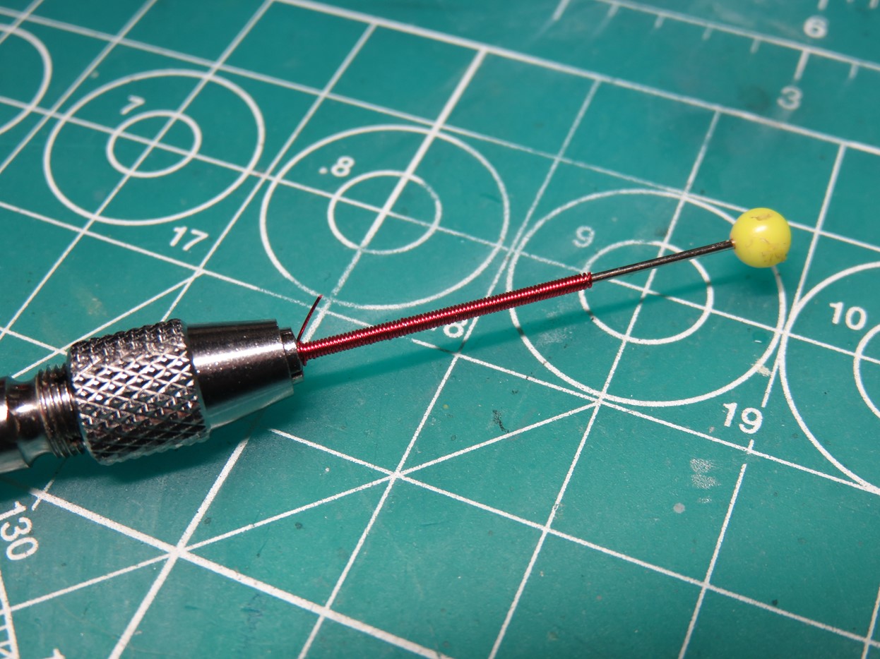
To create the springs, I took my pin vise and tightened a pin into the chuck. I then used some K&S Engineering 0.2mm music wire and slowly wrapped it around the pin to create the tiny springs. Once the wire was tightly wound up, I measured every 3 lengths and cut the spring into small sections.
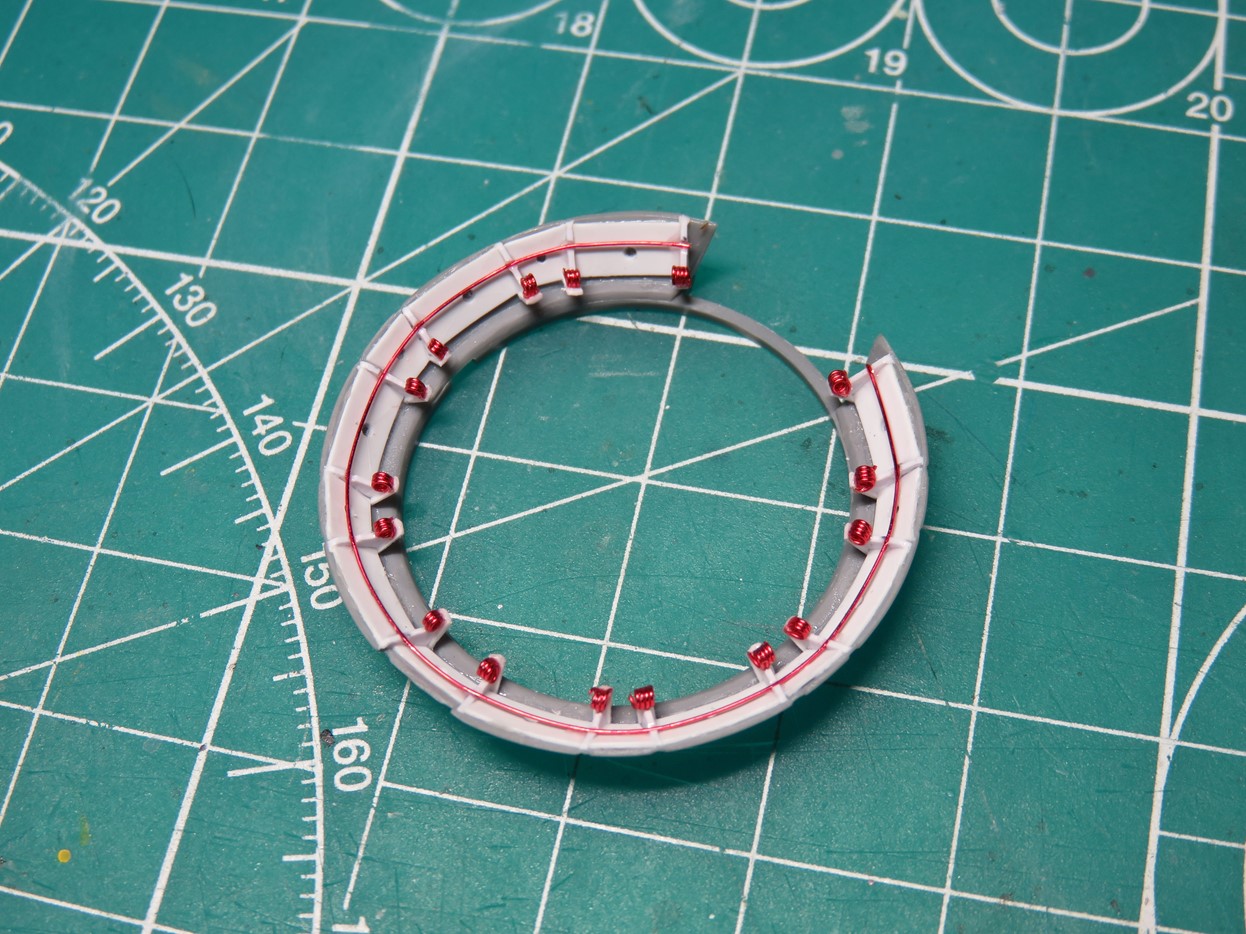
These small springs were then super glued onto the tabs all around the cowling. I was sure to make some extras as I did lose a few springs in the process. I also cut a small V-shaped grove into the triangles for the center wire that runs around and closes the cowl flaps.
I’ve test-fitted this part a few times to the fuselage and it looks really impressive. It might not look like too much at the moment, but once it’s primed, painted, and given a wash these little details are really going to stand out.
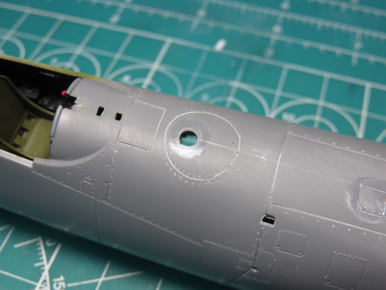
When I was scribing some of the details on the top of the fuselage I realized that I had sanded away the fuel cap. This is a part I really wanted to add back to the model. However, I don’t really have any good scribing tools to carve out a circle, as you can see from my first attempt.
So I decided that I’d rebuild the fuel cap, by first drilling out the center portion.
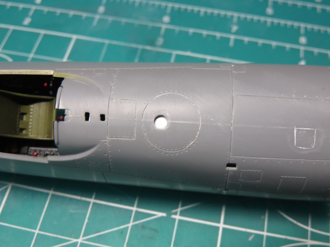
I then glued some styrene to the inside of the fuel tank. This was going to be the new base for the fuel cap.
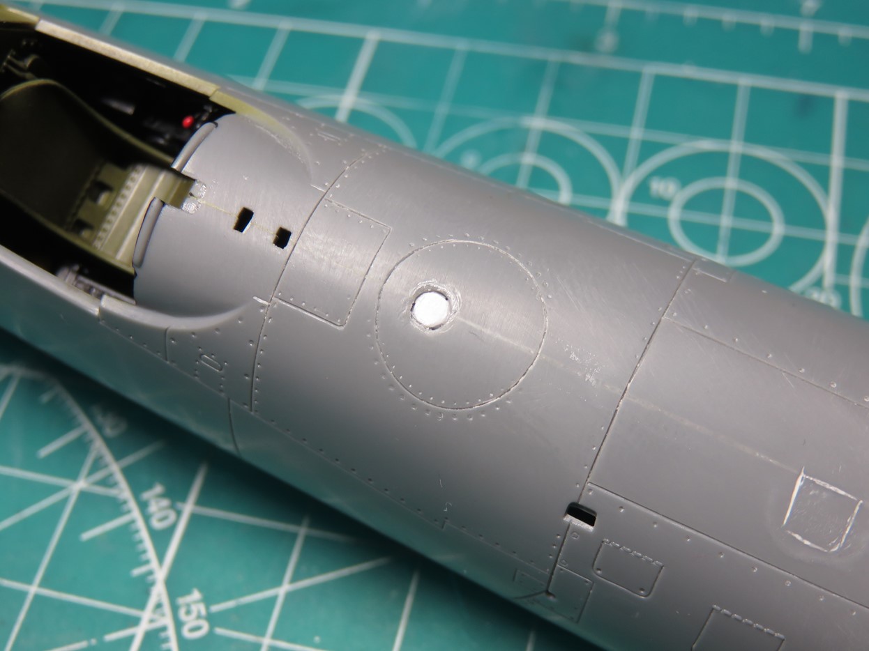
Using a leather punch I was able to punch out some disks out of styrene that were approximately the same size as the hole.
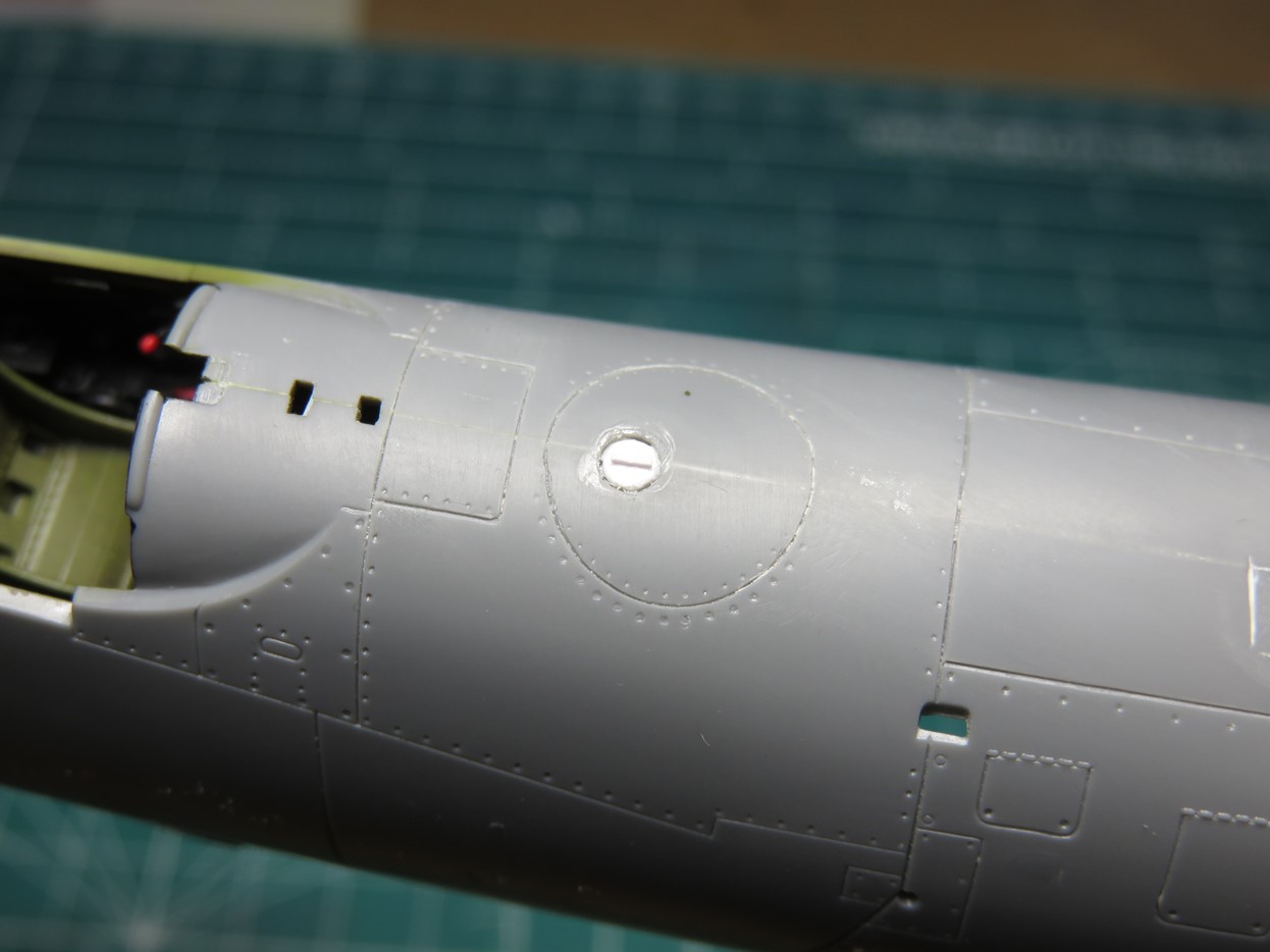
The fuel caps on the Corsair have a small raised handle, I replicated this as a very thin piece of styrene. It was very tricky to get it glued to the cap, but I did manage it in the end.
I’m glad that I decided to add these parts to the model. I’m really excited to paint the fuel cap red and see it stand out against the overall blue finish. As well, the headrest is going to look great with the seated pilot.
There is still a lot of work to be done, and I think I’m finally ready to begin working on the wings.
To be continued…
Jared Demes is a modeler from southern Alberta. He has been building models since he was 4 years old when his Dad first introduced him to the hobby. He has written for several magazines including, Fine Scale Modeler, Scale Aircraft Modeling, Phoenix Scale Models, and others. He has an interest in all modeling subjects, with a focus on WWII Japanese aircraft and Science Fiction.
Jared has won several IPMS awards for his modeling, and currently operates his YouTube channel rebelsatcloudnine, where he showcases model builds and product demonstrations.